Brushless motors have characteristics that make them excellent motors for speed control. In this section, we will explain the technologies that enhance the performance of these motors.
| 5.1 Wide Speed Control Range (Low-Speed Operation) |
We will explain the technology used to allow brushless motors to operate smoothly at low speeds.
5.1.1 Low Cogging Design
The pulsing vibration one feels when rotating a stepper motor shaft with one's finger while it is in a non-energized state is called the cogging torque.
Brushless motors use permanent magnets in their rotors, and the magnetic energy stored in the air gap between the rotor and stator changes depending on the rotor position. The angle at which the rotor teeth and stator teeth are positioned from each other alters the magnetic energy repeatedly; generating cogging torque along the way. If magnets with a high energy product are used, high cogging torque will also be created.
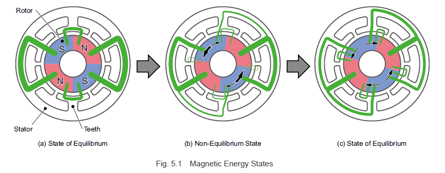
We will now explain rotor angles and magnetic energy states using the example of a motor with 4 rotor poles and 6 stator slots as shown in Fig. 5.1.
The magnetic flux generated in the rotor magnets passes through the iron core of the stator along the paths indicated by the green lines, flowing from the north pole to the south pole. The thickness of the line reflects the amount of magnetic flux, and the curvature of the lines towards the center reflects the unbalanced state of the magnetic energy. At this point, force is generated in the rotor in the directions (indicated by the black arrows) in which the magnetic flux attempts to flow so that it can become straight, or directly aligned.
In the state shown in Fig. 5.1 (a), all of the magnetic flux aims towards the center, and the magnetic energy for each slot is well-balanced. On the state shown in Fig. 5.1 (b) where the rotor has been rotated clockwise 7.5°, the balance of the magnetic energy between the teeth facing the south pole is lost, and torques are generated with directions and magnitude matching those of the black arrows.
The torque orientations are in the opposite directions, but torque is generated in the counterclockwise direction, where the generated torque is higher. In the state shown in Fig. 5.1 (c) where the rotor has been rotated clockwise another 7.5°, the balance of the magnetic energy between the teeth facing the south pole is lost, and torques are generated in the directions indicated by the black arrows. Torque generated in this state is negated by the torque of the same magnitude traveling in the opposite direction, and a cogging torque is not generated.
Cogging torque is also generated when the motor is operating.
While the motor is operating, it acts as a change in the load torque and exhibits smooth operation, so it is necessary to keep it low during the magnetic design. Up until now, a lot of research has been done on methods for reducing cogging torque.
The main methods for reducing cogging torque are as follows:
- combining an appropriate number of teeth with an appropriate number of magnetic poles
- making the rotor magnet arrangement or the magnetization of the magnet diagonal (rotor skew)
- laminating the stator such that it twists (stator skew)
- optimizing the shape of the magnets and stator
- optimizing the waveform of the magnet magnetization
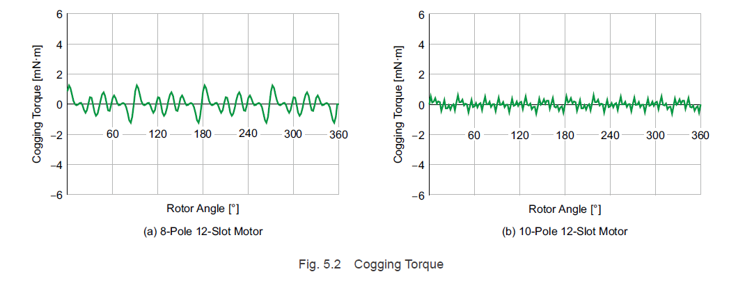
Combining an appropriate number of teeth with an appropriate number of magnetic poles is the most effective method for counteracting cogging torque. In general, the cogging torque period per motor rotation is the least common multipole of the number of magnetic poles and the number of teeth. In addition, the larger the least common multiple is, the lower the cogging torque becomes.
Fig. 5.2 shows a comparison of the cogging torques for an 8-pole, 12-slot motor and a 10-pole, 12-slot motor. The number of cogging torque cycles per motor rotation is 24 for the 8-pole, 12-slot motor, and 60 for the 10-pole, 12 slot motor. The cycles generated by the 10-pole, 12-slot motor are fine, and it is clear that the cogging torque decreases in amplitude.
Oriental Motor's brushless motors are the 10-pole, 12-slot type.
5.1.2 Sine Wave Drive
Utilizing sine wave drive decreases the amplitude of the torque ripples, and smooth operation is possible even during low speed rotation. While the principle is explained in "3.2.2 For a Sine Wave Drive System", here we will explain the prerequisites that form the crux of t his principle.
a. The Magnetic Flux Density That Acts on the Windings
The magnetic flux density that acts on the windings should ideally change so that it is a true sinusoidal curve, as shown in Formula (3.2). If distortion occurs in the sine waves, torque ripples are generated in the motor, which causes speed ripples.
The methods for creating the ideal waveform for the magnetic flux density are the same as the methods for reducing cogging torque, and include the following:
- the optimum combination of number of teeth and number of magnetic poles
- applying rotor skew or stator skew
- optimizing the shape of the magnets and stator
- optimizing the waveform of the magnet magnetization
However, because the shape that reduces the cogging torque is not the same as the shape that allows for the optimal magnetic flux distribution to be obtained, the design of the magnetic circuit takes balance into consideration.
b. The Motor Current Consists of Sine Waves
As shown in Formula (3.6), it is ideal that the current that flows through the motor consist of sine waves. Just as with the magnetic flux density, if distortion occurs, torque ripples are generated, which also causes speed ripples. To create the ideal current waveform, fine and accurate detection of the rotor magnetic pole positions is necessary. At Oriental Motor, Intermittent processing of the hall effect IC signals using software allows us to obtain rotor magnetic pole position information at a high resolution.
5.1.3 Speed Detection Accuracy
Brushless motors use speed calculators to convert the signals from the hall effect ICs into rotation speed and obtain information about the motor speed. Low-speed operation of a motor widens the signal detection intervals from the hall effect ICs, as shown in Fig. 5.4, and the motor speed detection value changes periodically. If there are ripples in the feedback speed detection value, ripples will occur in the voltage (current) commands from the speed controller, which results in ripples in the motor speed.
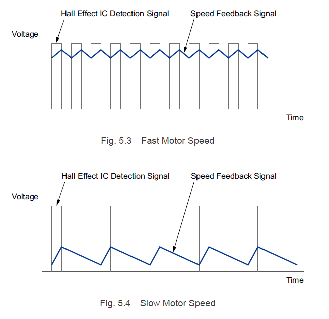
Oriental Motor's brushless motors have increased the hall effect IC signal frequency by a factor of 2.5 by increasing the number of magnetic poles in the rotor from 4 to 10. This makes the feedback signals during low-speed operation smooth, reducing the ripples in the motor speed.
Since brushless motors use sensors for detecting magnetic poles, they have not been suited to low-speed operation. However, improvements in magnetic analysis technology, software signal processing technology, and drive technology have lowered the minimum operating speed from 300 RPM in 4-pole motors to 80 RPM. In addition, the output torque is constant even at the minimum speed, enabling smooth rotational control in a wide range of speeds.
| 5.2 Wide Speed Control Range (High Speed Operation) |
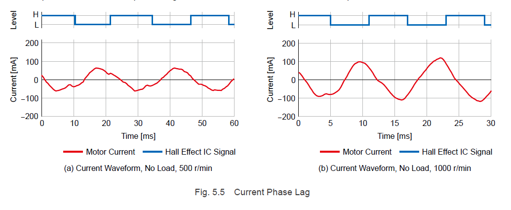
Hall effect IC signal waveforms and motor current waveforms are shown in Fig. 5.5.
Compared to 500 RPM, with regards to the hall effect IC signals, lag in the current waveforms and an increase in motor current can be observed at 1000 RPM.
When performing driving for brushless motors, voltage is applied to the windings in accordance with the hall effect IC signals and excitation patterns. However if the rotation speed increases, lag occurs in the current phases due to motor inductance. The lag that occurs in the current phases generates an ineffective electromagnetic force for the torque generated in the motor, decreasing the effective electromagnetic force. Because the motor performs control to maintain the rotation speed, the current is increased and the necessary torque is generated. Moreover, if the speed increases, the phase lag increases, and rotation ceases.
We will now explain the methods used to correct the current phase lag, which is necessary for making high-speed operation possible.
5.2.1 Output Torque Correction by Phase Control
Lead angle control allows for the output torque to be corrected by calculating the current phase lag according to the motor speed and advancing the voltage phase.
The value by which the voltage phase is advanced is called the "lead angle", a, and it can be calculated using the following formula:
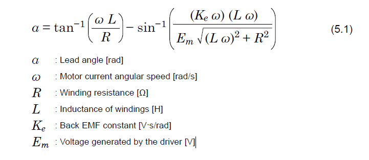
However, performing a calculation this complex requires a CPU with high processing power. For this reason, instead of using the formula as-is to perform the calculation, an approximate formula for the lead angle is used in the calculation.
The relationship between the lead angle and the rotation speed is shown in Fig. 5.6. In areas where the lead angle is large. Since it changes almost linearly with regard to the rotation speed, a linear approximation formula can be used to express the relationship between the lead angle and the rotation speed.
Similarly, the relationship between the lead angle and the applied voltage can also be expressed as a linear approximation, so the lead angle can be calculated from the rotation speed and applied voltage.
However, because using only the linear approximation results in the efficiency and torque decreasing due to excessive phase advancement during low-speed, high-load operation. In reality, a limit is imposed upon the lead angle value.
The advantages of this control system are that the circuit configuration is simple due to the current loop not being necessary and that there are few motor control adjustment elements.
5.2.2 Vector Control
Vector control is a control method that utilizes mathematical techniques to convert the currents that flow through the windings of a three-phase motor into a model equivalent to that of a DC motor, thereby simplifying control.
Currents that flow through phases U, V, and W of a brushless motor change constantly due to the motor torque and rotor rotation angle. Under these conditions, computational processing for current control is difficult. However, by converting a three-phase current into a two-phase current, and fixed coordinates into rotational coordinates, it is possible to split the current into the torque-generating component (q-axis component of current) and the magnetic flux-generating component (d-axis component of current), regardless of the rotor rotation angle.
In this state, by constructing a current loop to retrieve the detection values from the torque-generating q-axis component, and the magnetic flux-generating d-axis component of current adhere to the command value, the output torque and magnetic flux that passes through the windings (flux linkage) can be controlled at will.
Because the output torque and flux linkage can be controlled separately, the output torque and speed can be controlled with a high degree of responsiveness.
In addition, by controlling the flux linkage, it is possible to achieve maximum efficiency control for energy-saving operations. It is also possible to improve speed-torque characteristics, such as maximum torque control and field weakening control.
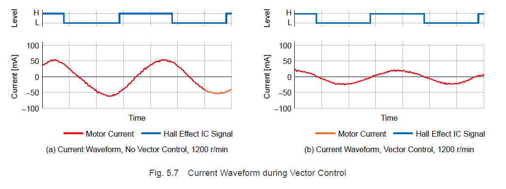
An example of a current waveform being improved through vector control is shown in Fig. 5.7. Fig 5.7 (a) shows the current waveform without vector control, and Fig. 5.7 (b) shows it with vector control. In the drive circuit, the motor current is controlled, such that it switches from negative to positive via the up edge of the hall effect IC output signal.
Without vector control, lag can be observed in the motor current.
In Fig. 5.7 (b), the hall effect IC signal up edge and current switching conform to one another, and the current phase lag disappears. In addition, performing vector control makes the motor current value smaller.
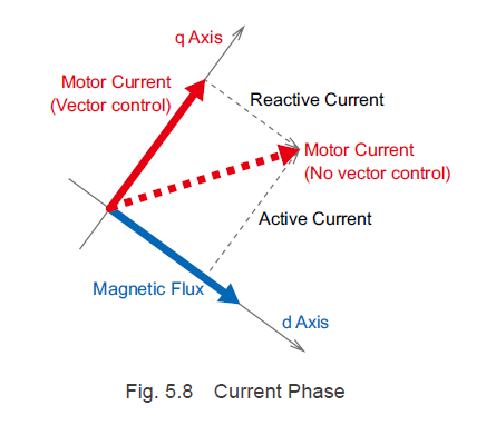
Displaying the states with and without vector control shown in Fig 5.7 as current vectors using rotational coordinates creates a figure l like Fig. 5.8 (when rotating counterclockwise).
When vector control is not performed, the orientation (indicated by the red broken line) in relation to the magnetic flux phase is less than 90°. In addition to the active current (q-axis component of current) component that acts as torque, the motor current also includes the reactive current component that does not act as torque.
When vector control is performed, the current flows in a 90° orientation in relation to the magnetic flux. Utilizing vector control to always keep the magnetic flux and current orientation at 90° eliminates current phase lag and reactive currents during high-speed operation and allows for efficient operation.
| TIP: Principle of vector control |
|
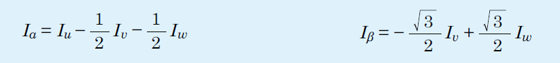
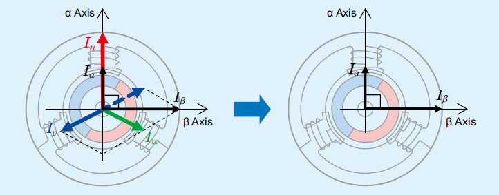
1. Detect motor current values Iw, Iv, and Iw. 2. Convert the three-phase current values into orthogonal 2-axis 2-phase current values [Clark's Transformation].
Values Ia and Ib change for each rotor angle.
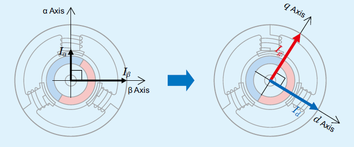
3. For the 2-phase current values, transform the coordinate system from fixed coordinates to rotational coordinates that synchronize and rotate with the rotor [Park's Transformation]. By transforming the coordinate system so that the d-axis orientation is fixed in the direction of the magnetic field, the current can be treated as a direct current just as DC motors that have rotating conductors, making the calculation much simpler.
Values Id and Ia are constants that are not related to the rotor angle Θ.
4. Compare the actual Id (d-axis component of current) and Iq (q-axis component of current) with the command value to find the difference. 5. Control the applied voltage in the current loop such that the current command value matches Id and Iq. |

5.2.3 Field Weakning Control
Field weakening control refers to increasing the motor torque during high-speed operation by weakening the magnetic flux of the part (field) that generates magnetic flux by controlling the d-axis component of the current.
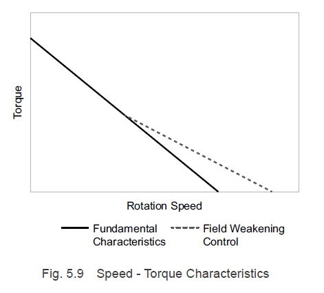
The fundamental characteristics of brushless motors are sloping torque characteristics such as those shown in Fig. 5.9. The torque generated in the motor is proportional to the motor current, so the higher the speed, the smaller the current value. We will explain the reasons for this below.
The voltage in each area when a brushless motor is rotating is represented by the below formulas.
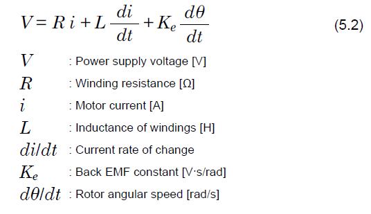
The left side of Formula (5.2) indicates the applied voltage, the first term on the right side is the voltage applied to the winding resistance, the second term is the voltage due to the inductance component, and the third term is the back EMF.
From Formula (5.2):
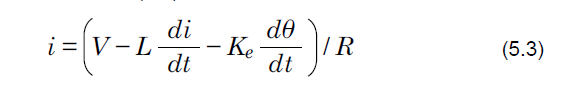
As indicated by Formula (5.3), if the motor rotation speed increases, the inductance component causes an increase in the voltage drop and the back EMF rises, decreasing the motor current. For this reason, the brushless motor speed-torque characteristics are sloping characteristics such as shown in Fig. 5.9.
By performing field weakening control during high-speed operation, making the current flow in the d-axis negative direction, and weakening the field's magnetic flux, it is possible to lower the back EMF generated in the windings.
Because the current becomes larger when back EMF decreases, the generated torque increases. This allows the speed range used during high-speed operation to be expanded (Fig. 5.9).
| 5.3 High-Accuracy Speed Control |
5.3.1 Speed Regulation
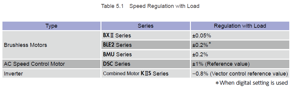
Speed regulation is an important specification for motors used for speed control. It's defined as the rate of speed variation when the load torque, power supply voltage, ambient temperature, or other factors in the usage environment change while the motor is operating at a set speed.
Oriental Motor's specification uses the rate of speed variation at the rated rotation speed when the following conditions are changed. Therefore, if the rated rotation speed is 3000 r/min and the speed regulation is +/-0.2%, the speed variation is +/-6 RPM.
Since speed fluctuation range depends on sensor detection accuracy, even if the operation speed is not 3000 r/min, the speed variation amount may still be approximately +/-6 RPM (at the motor shaft).
With Load: when a rated load is applied, assuming a no-load state
With Voltage: when the voltage changes within the allowable range, assuming a rated voltage
With Temperature: when the temperature changes within the ambient operating temperature range, assuming an ambient temperature of 25°C.
A brushless motor controls the motor speed in a closed-loop; based on the feedback speed calculated from the hall effect IC signals. The increased number of signals from the hall effect IC due to the rotors multi-polarity increases the detection accuracy of the rotation speed, resulting in low speed regulation, and allowing for operation at a speed close to the commanded speed.
With inverters (VFDs) that do not have a speed detector and perform sensorless speed control, rotation speed changes due to the changes in rated torque.
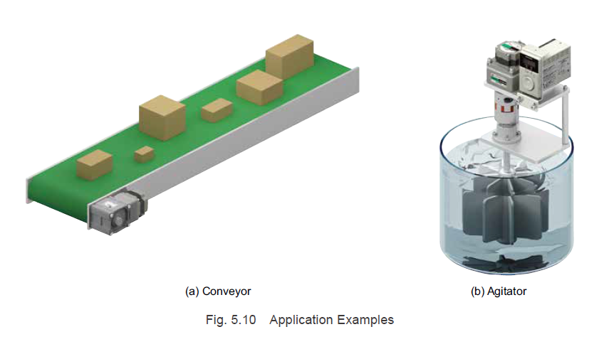
Due to accurate speed regulation, stable operation is possible through a conveyor with variable loads and weights, such as an agitator or discharge pump in which the liquid viscosity changes, and so on. In addition, this is appropriate for coating, heating, and other applications in which a fixed processing time is desired during conveyance.
| TIP: Differences between speed regulation and flutter characteristic |
|
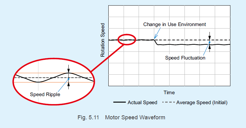
Besides speed regulation, flutter characteristic is another characteristic that demonstrates motor speed stability. Speed Regulation: the average speed fluctuation ratio generated when the usage environment changes Flutter Characteristic: the speed ripple ratio for the average speed during rotation at a constant speed.
Speed fluctuation refers to the average speed of the motor itself changing, while speed ripples refer to the actual breadth of the speed changes when the average speed is constant. Speed ripples are generated by torque ripples during a single motor rotation or by performing speed control. With image inspection equipment, they appear as screen shaking, and with coating equipment, they appear as coating inconsistency. |
5.3.2 High Reliability
In addition, by utilizing overload information and the overload warning function, it is possible to detect increased loads before the overload alarm activates. This allows the prevention of sudden production line stoppage and for systematic maintenance. We previously explained that since brushless motors control the motor speed in a closed loop based on the feedback speed calculated from the hall effect IC signals, the speed regulation is low and stable operation is possible.
Because the motor speed is always being monitored, if for some reason an excessive load is applied and the speed decreases, or if the motor stops, an alarm signal is output, making it possible to detect malfunctions.
| 5.4 Stable Stop Position |
When performing high accuracy positioning operations, in general, stepper motors and servo motors are used for their excellent positioning accuracy. However, depending on the required accuracy and usage methods, it may be possible to satisfy the requirements for positioning accuracy even with simplified positioning operations with inexpensive speed control motors or AC motors.
When stopping conveyed objects and rotated objects at a target position is desired, speed controllers and drivers with an instantaneous stop function are used. However, to detect conveyed objects, it is necessary to install a sensor at the stop position and perform control with a programmable controller and so on.
When a stop signal is input, the motor overruns and stops due to the effect of the rotor moment of inertia and the load moment of inertia. At this time, the overrun amount decreases according to the level of friction torque in the device.
5.4.1 Overrun Amount
The braking characteristics for a DSC Series 25 W AC speed control motor and a BLE2 Series 30 W brushless motor are shown in Fig. 5.12.

These braking characteristics show the relationship between the load inertial moment and the overrun amount (average value) when there is no friction load. Since the rotational energy is greater at high speeds or with a large inertial load, the overrun amount will also increase.
5.4.2 Variation in the Overrun Amount
Both AC speed control motors and brushless motors have variations in their overrun amounts. Fig. 5.13 shows the variation in overrun amount when the motors repeatedly operate and brake 100 times with the load inertial moment J set to 0.251 x 10^-4 kg-m² and the rotation speed set to 1000 r/min.
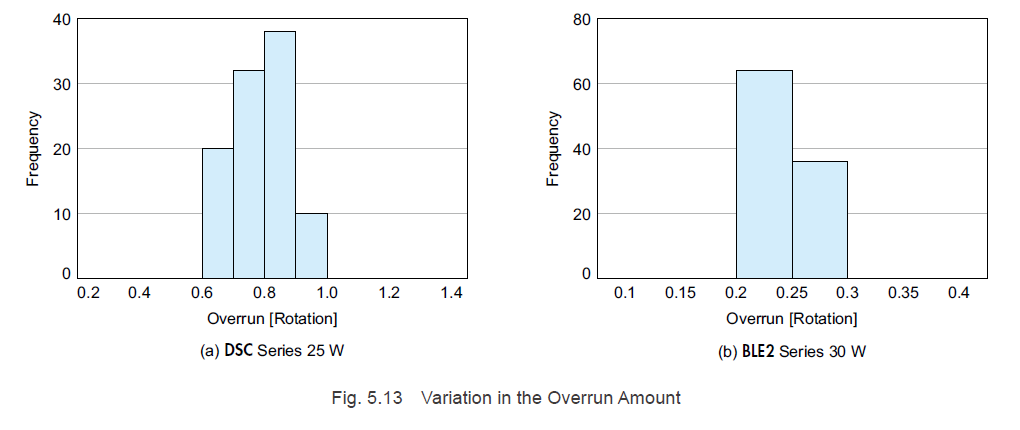
Many AC speed control motors and brushless motors are used in combination with gearheads.
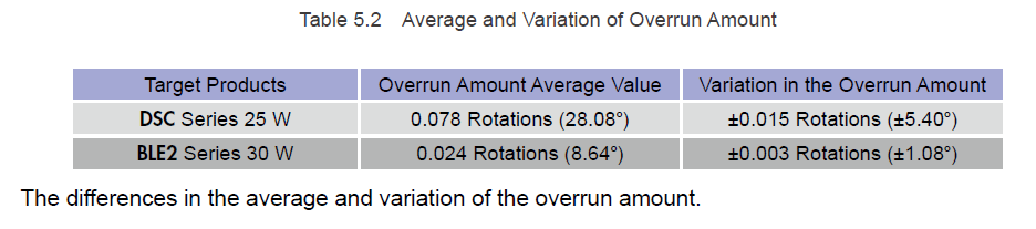
For example, when combined with a gearhead with a reduction gear ratio of 10, the average overrun amount and its variation measured at the gear shaft are reduced to the values shown in Table 5.2. However, 1° to 2° of backlash in the gear should be added to these values.
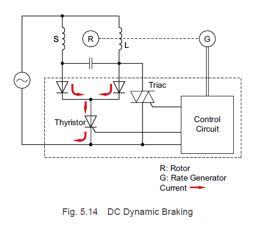
5.4.3 AC Speed Control Motor Braking Method
AC speed control motors control the voltage applied to the motors via triac-based firing angle control. When a brake signal is input, the triac switches OFF, and the thyristor turns ON for a fixed amount of time. As indicated by the red arrows in Fig. 5.14, an in-phase current that has undergone half wave recitification in the main winding (L) and auxiliary winding (S) of the motor flows through the diode. This causes DC braking (AKA dynamic braking) to be performed, which stops the motor instantaneously.
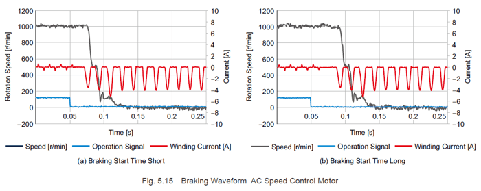
Due to the timing of the brake signal input in the power supply voltage phase, the time when the braking current begins to flow (braking start time) lags behind the power supply frequency by one cycle at most. For this reason, variation occurs in the overrun amounts.
The relationship between the operation signal, the braking current, and the motor speed is shown in Fig. 5.15. Comparing the left and right figures, a gap of one power supply frequency cycle can be observed from the time when the operation signal switches OFF (brake signal ON) until the braking start time and the motor stops.
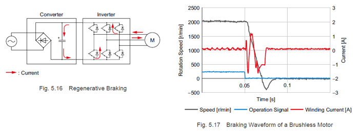
5.4.4 Brushless Motor Braking Method
As explained in "4.5 Braking (Regenerative Operation)", a brushless motor works as a generator during braking, and braking torque is generated by converting the rotational energy into electrical energy as shown in Fig. 5.16. If you look at Fig. 5.17, regeneration current flows through the windings directly after the operation signal switches OFF (brake signal ON). Because braking torque can be generated without being affected by the timing of the brake signal input in the power supply voltage phase, the stop position is stable.
|
Previous Post
|
Next Post
|


Learn more about Oriental Motor's 
Subscribe (top right corner) to receive monthly updates!