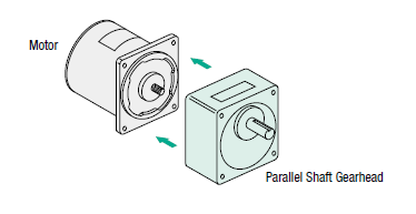
By adding a gearhead to a motor, a motor becomes a gear motor, and its torque is multiplied by its gear ratio and gear efficiency. However, beyond increasing torque, there are many other advantages to using gear motors.
|
Why use geared motors?
|
✅High Torque Output
When a geared motor is used, the motor's torque is multiplied by the gear ratio and gear efficiency. A geared motor will output more running and holding torque than an ungeared, standard motor. Along with higher torque output and strengthened rigidity, many related benefits can be realized as I will discuss below. It all starts with torque.
Geared motor torque = motor torque x gear ratio x gear efficiency
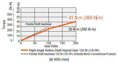
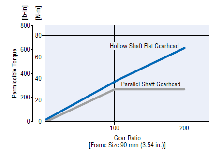
Here we show a chart that depicts the relationship between torque and gear ratio. As gear ratio increases, so does torque. For most gearheads, there is a limit on maximum permissible torque, so the line flattens out when a certain gear ratio is exceeded.
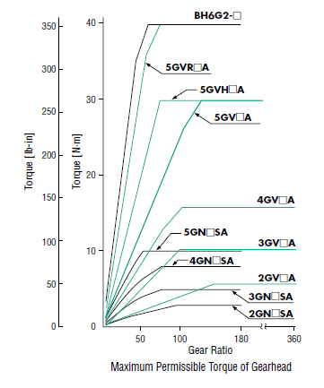
For certain gearheads, such as hypoid or FR hollow shaft flat type, there is no limit on permissible torque, so the line doesn't flatten out.
| Hypoid Geared Motor | FR Hollow Shaft Flat Geared Motor |
 |
 |
| TIP: Gears for Different Types of Motors |
|
Gear efficiency differs by gear design. Different types of gears are designed for different motors that are used in different scenarios. For example, worm gears and hypoid gears are typically offered with AC motors and brushless motors that are designed for constant speed or variable speed operation. Backlash isn't an issue for these motors. However, since stepper motors and servo motors have to handle dynamic loads and quick stops with high precision, they use highly efficient planetary or harmonic gears with low backlash. A hybrid gearhead (harmonic-planetary) is also available, which combines features from both harmonic and planetary gear designs and presents an alternative between harmonic and planetary gears. |
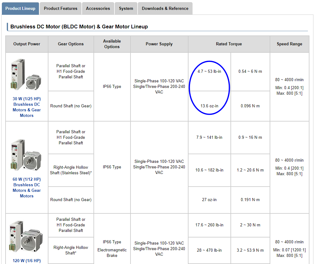
Torque ranges of different types of motors are listed by frame size. This chart below is shown on every product overview page under the "Product Lineup" tab. As you can see, for a 30 W brushless motor, the rated torque is only 13.6 oz-in. However, the torque can increase up to 53 lb-in with a 200:1 parallel shaft gearhead.
Example: BLE2 Series Brushless Motors Torque Range Chart (Website)
✅Speed Reduction
Gearheads are also referred to as "speed reducers". Gear ratios are sometimes referred to as "speed reduction ratios". While speed controllers take care of speed reduction nowadays, gearheads were used to reduce the speed of a motor in the ancient past. When a geared motor is used, the motor's speed is divided by the gear ratio. For example, an 1800 RPM AC synchronous motor with a 5:1 gearhead will run at 360 RPM.
Speed of gearhead shaft = motor shaft RPM / gear ratio
| TIP: About Gear Ratios |
|
A gear ratio can be the ratio between the speeds, circumference, or teeth of 2 gears. It typically describes the ratio between the motor shaft and the gearhead shaft, or it can be used to explain relationships between gears inside the gearhead. For example, a gearhead that has a 3:1 gear ratio means there is a speed reduction ratio of 3:1 between the speeds of the motor shaft and the gearhead shaft. However, inside the gearhead, there may be multiple stages of gears. Individual gear ratios are multiplied to determine the final gear ratio.
|
FYI we typically show both the torque and speed for each gear ratio in our literature. At gear ratios of 120:1 to 360:1, the maximum permissible torque is reached. Therefore, this motor should not drive anything that requires 141 lb-in (16 Nm) of torque or more. Exceeding this specification may degrade the life of the product. Another thing know is that for AC motors, the variation in inertial load can cause the speed to decrease slightly from the designated RPM. This is different than other motors.
Example: AC Motor Torque-Speed Table (Catalog)

| TIP: Decimal Gearheads |
| If additional speed reduction is necessary, and you have the space, use a decimal gearhead along with a standard gearhead to achieve a 2-stage speed reduction. However, the permissible torque limit does not increase. To calculate the resulting gear ratio for a 2-stage gear reduction, multiply the gear ratios together (ie: 360:1 x 10:1 = 3600:1). |
✅High Resolution
When I started supporting motion control applications a long time ago, some customers actually used gearing to increase their stepper motor resolution. From what I remember, I believe they wanted to avoid purchasing a bipolar microstepping driver, which was more expensive at the time.
Geared motor resolution = motor resolution (steps/rev) x gear ratio
For example, a standard 200 steps/rev stepper motor with a 5:1 gear ratio will require 1,000 steps to rotate one revolution at the gearhead output shaft. The fine resolution allows the motor to step at a smaller increment for fine positioning applications. Microstepping will take care of most high resolution requirements these days.
✅Drive Large Inertial Loads
When a geared stepper motor or servo motor is used, the inertial load that can be rotated increases by the square of the gear ratio in comparison with an ungeared motor of the same size. Bascially, you can drive an exponentially bigger inertial load with geared motors.
When using different types of motors, pay attention to how the inertial load is treated. We show some examples below.
For AC motors, we follow this formula below. When gear ratios are less than 3:1~50:1, we multiply the rotor inertia by the gear ratio squared. For gear ratios of 60:1 or higher, we only multiply the rotor inertia by 2500 as there is a limit.
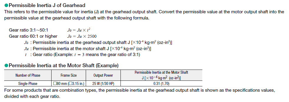
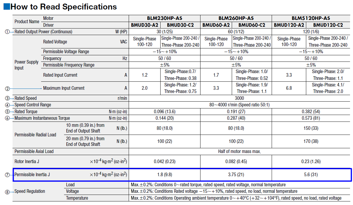
For brushless motors, the "Permissible Inertia J" value is shown on the website and literature (7). These values are based on tests. Permissible load inertia increases with the motor size and wattage.
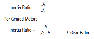
For stepper motors, it gets a little more complicated and requires some calculation. In addition, open-loop and closed-loop stepper motors can handle varying amounts of load inertia. The reason is because of something called the "inertia ratio". An inertia ratio is a reference given by a motor manufacturer to quickly determine if the inertial load can be driven by the motor.
For ungeared motors
Calculated load inertia / rotor inertia = inertia ratio
or
Max load inertia that can be driven = rotor inertia x max permissible inertia ratio
For geared motors
Calculated load inertia / rotor inertia x gear ratio² = inertia ratio
or
Max load inertia that can be driven by steppers = rotor inertia x gear ratio² x max permissible inertia ratio
The maximum permissible load inertia for stepper motors is calculated by the formula above. For every stepper motor (or servo motor), it is recommended that the inertia of the load stays under this value. If this value is exceeded, then issues such as missed steps may occur.
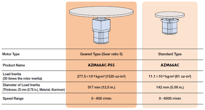
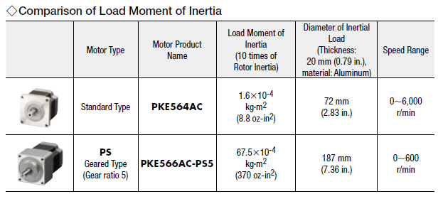
The recommended maximum permissible inertia ratio for open-loop stepper motors is 10:1. This increases to 30:1 for closed-loop stepper motors. For servo motors as a comparison, the maximum permissible inertia ratio is 50:1 by auto-tuning and up to 100:1 with manual tuning.
Example: AlphaStep stepper motor (closed-loop)
Example: standard stepper motor (open-loop)
✅Shorter Positioning Time
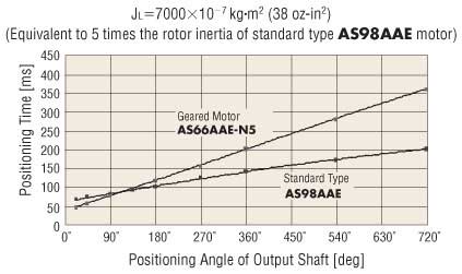
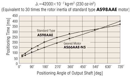
For large inertial loads, the use of a geared motor will achieve a shorter positioning time than a standard type motor. In the graphs below, we compare the fastest positioning time between an ungeared closed-loop stepper motor and a geared closed-loop stepper motorat 5:1 inertia ratio and 30:1 inertia ratio.
As you can see, at 5:1 inertia ratio, the geared motor takes longer than the standard type. However, at 30:1 inertia ratio, the geared motor can position faster until a certain point (540°).
| At 5:1 Inertia Ratio | At 30:1 Inertia Ratio |
 |
 |
✅Downsize
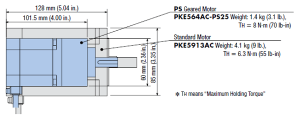
Since a gearhead can increase a motor's torque dramatically, a smaller geared motor can output equivalent torque as a bigger, ungeared motor. In some cases, geared motors can offer downsizing benefits to machine design. See an example below for a comparison between an equivalent NEMA 34 size standard stepper motor vs a NEMA 23 geared stepper motor.
Standard motor vs geared motor
✅Improved Damping Characteristics
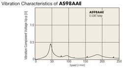
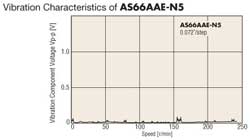
If the inertial load is large or acceleration/decleration rate is high, a geared motor can increase damping effects more effectively. This ensures more stable operation compared to an ungeared motor; especially during starting and stopping. Geared motors are ideal for applications where a large inertial load, such as an index table, must be driven.
Vibration Comparison
| A NEMA 34 Ungeared Motor | A NEMA 23 Planetary Geared Motor |
 |
 |
Application Examples for Geared Motors
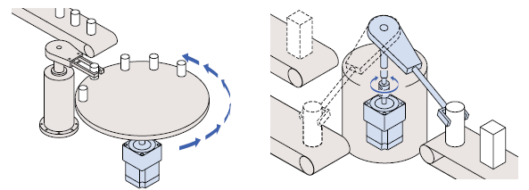
✅Increased Axial and Radial Load
Both axial (thrust) and radial (overhung) loads are also increased due to the enhanced strength and rigidity of a geared motor. For example, axial load and radial load for a 25W KII Series AC induction motor increase to 101 lbs and 22 lbs respectively.

As a comparison for a round-shaft, ungeared motor, the permissible axial load (thrust load) is only half of its mass, and the permissible radial load (overhung load) is less than 1/4 when compared with the geared motor.
✅Increased Rigidity
Geared motors have increased rigidity and are resistant to torsional forces. Therefore, compared to standard motors, geared motors are less subject to issues caused by load torque fluctuations. High stability and position accuracy can be expected even when there are fluctuations in load. For example, the increased gear friction of a geared motor provides more holding torque for a security camera to stay in position even with strong winds.
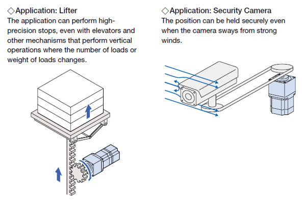
✅Surface Installation of Load (HS/HPG Harmonic Gear Type)
As an additional benefit, harmonic geared motors offer mounting holes right on the rotating surface of the gearhead for easy, direct installation of rotary tables or other types of load. This saves time and energy by eliminating unnecessary parts and processes and also improves reliability in some cases.

|
TIP: Learn more about gear technologies for stepper motors |
|
Learn more about the types and benefits of |
Gears 'R Us
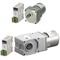
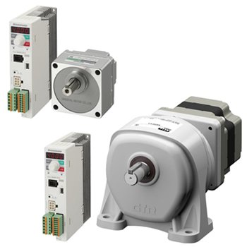
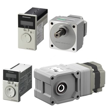
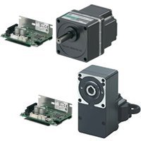
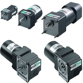
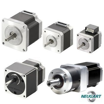
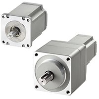
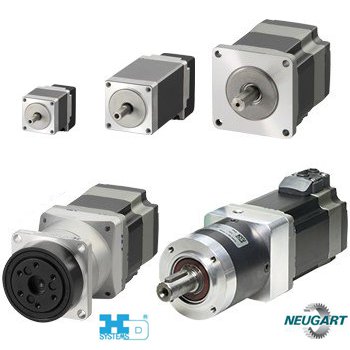
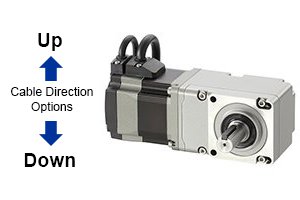
In recent years, Oriental Motor has expanded its own geared motor lineup as well as products from our industry partners such as Harmonic Drive and Neugart. Together we offer a massive gearhead selection for various types of motors. A great advantage of working with a manufacturer that provides both the gearhead and the motor is that all torque values for each gear ratio is already calculated, and that products have already been tested together. In addition, many of them are sold as pre-assembled units for quality, consistency, and reliability out of the box.
 |
 |
 |
 |
 |
 |
 |
 |
 |
Need help with geared motor product selection?
 |
 |


