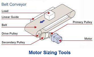
An AC motor is not working like it's supposed to. What do you do? Before replacing the motor, here are three ways to start troubleshooting your AC motor with a circuit tester.
AC motors are the easiest type of motors to use. Once power is connected, an AC motor runs at a certain speed, and stops when the power is disconnected. When an AC motor does not work, it's usually a power or wiring issue. The trick to identifying the cause is to isolate potential problems.
What is a Circuit Tester?
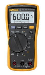 |
A circuit tester (also known as a multimeter or multitester), is an electronic measuring instrument that combines functions from a voltage meter, an ohmeter, and an ammeter. A typical circuit tester can measure voltage, resistance, and current in a circuit. |
First, Check the Basic Wiring.
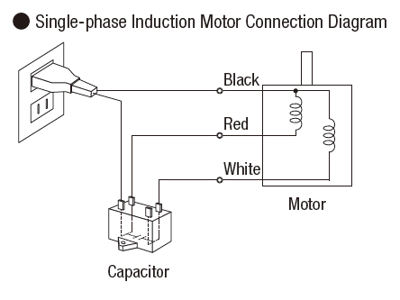
When the motor is wired to a power supply but not working, the first thing you should do is check the wiring and confirm the required components for operation are in good working condition. Since there could be many components in the power supply circuit that can affect motor operation, such as relays, switches, or controllers, start with the most basic circuit as possible. This means connecting the AC motor and capacitor directly to the AC power supply. Once you confirm that the motor works, then you can add back the components back. This can help you verify if the components are good or bad.
| TIP: Many AC motor issues are caused by bad components or incorrect wiring. To make troubleshooting easier, isolate the problem by troubleshooting the most basic circuit first. Once that has been confirmed, then test each individual component as they're added back into the circuit. |
3 Things to Test with a Circuit Tester
Here are three ways to help find the cause of an AC motor problem.
|
1. Compare the applied voltage with the capacitor's terminal voltage. |
Now we will show you how to do each measurement, and what it confirms.
| TEST 1: Compare Applied Voltage with Capacitor Terminal Voltage |
If properly connected, the capacitor terminal voltage should be roughly 1.7 times the value of the power supply voltage. This confirms if the motor is receiving the proper voltage.
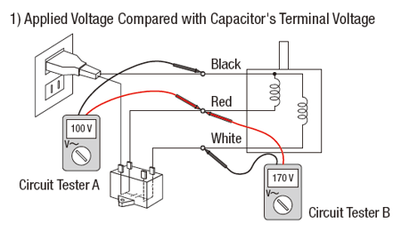
Using Circuit Tester A as shown in the above diagram, connect the red needle tip to the exposed portion of the red wire, and connect the black needle tip to the exposed portion of the black wire (and make sure there is good contact). Confirm that the proper voltage is received at the motor. Select AC voltage measurement mode (indicated by a "V"), on the circuit tester before starting. If correctly connected, Circuit Tester A will show the power supply voltage. For easy calculation, we used a 100 VAC motor in the example, so 100 V would display on the circuit tester.
Using Circuit Tester B as shown in the above diagram, connect the red needle tip to the exposed portion of the red wire, and connect the black needle tip to the exposed portion of the white wire. If properly connected, the circuit tester will show a value that's about 1.7 times the power supply voltage. In this example, 170 V is measured.
Compare the two measured voltages. The capacitor terminal voltage (red/white) should be 1.7 times more of the power supply voltage (black/red).
What If I Don't Have a Circuit Tester / Multimeter?
To check whether any capacitor is connected in the circuit, rotate the motor shaft manually by hand while the power is on. If no capacitor is connected, it will rotate in the direction in which you apply the force.
REVIEW:  |
| TEST 2: Verify if Electricity is Conducted Throughout the Cable |
A break in the connection of the motor's circuit with its power supply can prevent the motor from working properly. Doing the following measurement can confirm if a circuit is closed or open.
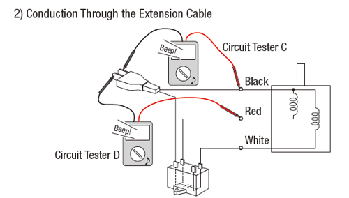
Do this with the power off. Using Circuit Tester C and D as shown in the above diagram to test the continuity of the cables from the motor to the power supply. Use the black and red needle tips from the circuit tester to connect to the exposed connection points closest to the motor to the power supply. If there's no break in the circuit, the circuit tester will beep.
| TEST 3: Verify Motor Winding Resistance |
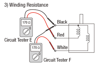
By measuring the motor's winding resistance and comparing the values to the motor's original designed values, the electrical condition of a motor can be verified.
Before measuring, remove all additional components, such as extension cables and capacitor, from the circuit. Switch the circuit tester to resistance value measurement mode. Using Circuit Tester E and F in the above diagram, connect to the exposed portions of the lead wires directly from the motor.
We are once again using a 100 V motor as an example (model: 2IK6A-JA). For this particular motor, the resistance readings from both Circuit Tester E and F should be 170 ohms. If the winding is broken, the circuit tester will read a value of over several thousand ohms. If there's an internal short circuit, a value smaller than 170 ohms. For other motors, please contact the motor manufacturer to see what the designed values are supposed to be. There is a tolerance of about +/-10% for winding resistance.
What Do I Do If My Motor Does Not Pass These Tests?
When a motor doesn't work, it could be a bad motor, or just a bad component making the motor look bad. Examples are bad switches, relays, cables, or just the wrong voltage. Doing these tests would provide valuable hints on what to fix. These are examples.
|
If your motor doesn't pass Test 1, check/replace the capacitor or wiring. If your motor doesn't pass Test 2, check/replace the cable or connector. If your motor doesn't pass Test 3, replace the motor. |
Mechanical issues, such as a damaged ball bearing due to excessive radial or axial loads, can also cease the operation of a motor. To test this, remove the motor and gearhead and try to rotate the shaft in both directions. If the motor shaft or the gearhead shaft feels locked up without any load, then something is not right. An abnormal noise or friction while turning the shaft could indicate damage or misalignment. The best thing to do would be to replace the motor and/or gearhead.
Another way to become a better motor troubleshooter is to understand the product better. Take a look at these related posts to increase your product knowledge of AC motors (or talk to our technical support engineers).
|
Related Posts: |