An AC motor can be simple to use, but its speed changes according to the size of the load or amount of voltage supplied. For an application where keeping a uniform speed is important, there is another type of motor that can improve performance.
First, let's understand how an AC motor determines its "rated torque" and "rated speed". Rated torque and rated speed is where the motor will perform most efficienctly for given voltage, motor, and load. The relationship between torque and speed are shown on a speed torque curve, which depicts expected performance of a motor. The motor either speeds up or slows down according to the load torque. It is ideal to size a motor properly so you can operate closer to maximum efficiency (rated torque and rated speed).
Look at the speed-torque curve below for an AC induction motor. When you supply power to an AC motor, the motor starts running from 0 RPM, gradually increases speed until it enters the stable region, then settles at the "rated speed". This rated speed is somewhere below the "no load speed" and "synchronous speed" and is determined by the load torque applied to the motor. If you draw a horizontal line from the rated torque value on the Y-axis to the stable region of the curve, rated speed is where it intersects the curve. 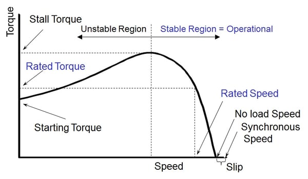
Mathematically, here's the formula that determines the "synchronous speed" of the motor.
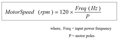
Oriental Motor manufactures both 2 and 4 pole AC motors. For a 3-phase AC motor with an input voltage of 220VAC, 60 Hz, the motor's synchronous speed (RPM) = 120 x 60 / 4 = 1800 RPM. Synchronous speed is essentially no load speed with the slip. Since applying a rated load would slow down the motor to its rated speed, the difference between rated speed and synchronous speed is the existence of the rated load.
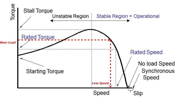
However, if the torque increases due to varying load mass, such as a box conveyor at the post office carrying loads of varying weights, the required torque would increase (force x radius of pulley), and you will no longer operate at the rated torque line. Instead, the motor speed fluctuates up and down along with changes in load torque. The graph below shows an example where increased friction load would slow down an AC motor.
|
Remember when I said a speed torque curve is for a given voltage, motor and load? Now let's see how a fluctuation of input voltage may change the curve. Higher voltage generates higher torque by pushing the curve upward and vice versa. Speed and acceleration performance are also affected by a change in available torque. FYI: if you have an AC motor that fluctuates in speed with the same load, then one of the first steps in troubleshooting would be to verify if the motor's input voltage is fluctuating. |
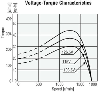 |
|
|
That's enough theory for now. Some variable frequency drives would offer vector control and motor slip compensation to reduce speed fluctuations and regulate voltage output to the motor, but fine tuning the motor parameters takes time. There is another plug and play solution that can help.

In this application example, we look at a parts feeder (vibrating feeder bowl) that's using an AC motor.
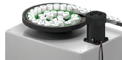
The parts feeder arranges the loads in a given direction and sends to the next production process by vibrating the feeder with a 3-phase AC induction motor. A VFD (inverter) is used for speed control.
Common Problems:
- The feed speed changes due to input voltage fluctuations for the motor.
- Varying loads could also change the feed speed.
- Precise adjustment of the speed for varying loads is difficult.
| The solution that can eliminate all of these problems is a permanent magnet brushless motor with feedback control. Oriental Motor's brushless motors are paried with dedicated drivers for optimal performance and closed loop speed regulation at +/-0.2% or better. Higher efficiency, compact size, lower operating temperature, and constant torque are other benefits of brushless motors that can help improve performance as well. |
|
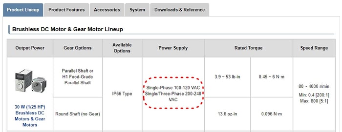
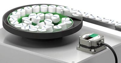 The dedicated driver can accept a wide range of input voltage and regulate its output to the motor. An example of our 30W BMU Series is shown below. If you look at the power supply specifications, you will see a wide range of input voltages. As long as the input voltage is within this range (100~120VAC), the same performance can be expected.
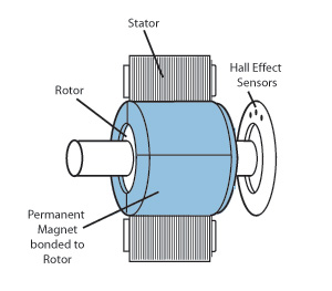
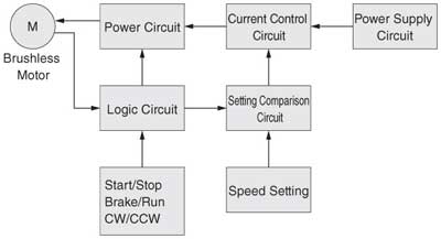
The feedback control is achieved with built-in hall effect sensors in the motors. The signals from the hall effect sensor are used for both measuring the speed of the motor as well as for the timing of the stator excitation sequence. The dedicated driver achieves better speed regulation by always comparing command speed (set speed) to actual speed (speed calculated by hall effect sensor pulses). If the speed is outside the tolerance, speed corrections are made instantaneously on the fly.
 |
 |
AC Motor vs Brushless Motor Performance Comparison:
With its permanent magnets, digitized PWM (Pulse Width Modulation) control, regulated voltage, constant torque, and feedback control, brushless motors offer stable speed control and the following improvement over AC motors and VFDs.

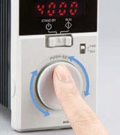
The speed regulation is measured at rated speed. For a brushless motor, the rated speed is typically higher at 3,000 RPM. For an AC motor, it's at around 1500 RPM. If we calculate this out, the fluctuation of the 3-phase AC induction motor is about 150 RPM, and the brushless motor is at 12 RPM (+/-6 RPM).
Furthermore, the speed can be precisely set digitally in 1 RPM increments. Use the potentiometer on the front panel of the driver to easily change speeds, then push to set.
For general purpose applications, AC motors would suffice. However, for more advanced applications where speed consistency, smaller footprint, or efficiency is critical, it's good to know that there's another solution in the market.
To learn more about brushless motors vs other types of speed control technologies, please read our white paper,  . . |


