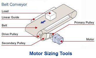
Automating screw tightening is no longer just about speeding up assembly; it’s also about ensuring consistent quality, reducing defects, and enabling scalable production. For automation engineers, one of the most effective architectures for achieving this is a multi-axis Cartesian system that combines precise positioning, controlled pressing, and accurate torque delivery.
In this article, we’ll walk you through how a 4-axis automated screw tightening machine can be built using electric linear actuators, and how Oriental Motor’s integrated motor and actuator solutions can simplify designs while improving performance.
Topics Covered:
✅ The Challenges of Screw Tightening Automation
✅ System Architecture: A 4-Axis Approach
✅ X-Y Axes: High-Rigidity Positioning with Electric Linear Slides
✅ Z-Axis: Controlled Pressing with Electric Cylinders
✅ Screw Tightening Axis: Torque Control and Quality Assurance
✅ Smarter, Unified Control Across All Axes
✅ Design Best Practices
✅ Why Electrification is the Answer for Modern Screw Tightening Systems
The Challenges of Screw Tightening Automation
Screw tightening/fastening seems simple - basically just rotate a screw until it cannot be rotated anymore, right? Yes, it is, but in automated environments, it introduces several technical challenges:
- Positioning accuracy must be maintained across multiple axes
- Reaction forces during tightening can deflect the structure
- Over-tightening or galling can damage parts
- Inconsistent pressing force can affect thread engagement and assembly quality
These issues make it critical to design a system where mechanical rigidity, motion control precision, and torque control all work together seamlessly.
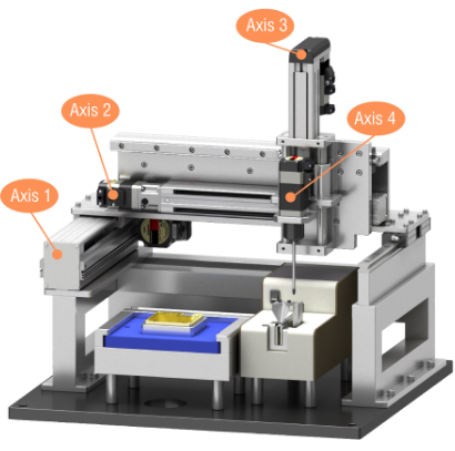
Here's an application example of a screw tightening machine with a screw tightening axis on the end-effector of a Cartesian (XYZ) robot.

Machine Specifications
| Number of Axes | 4 axes |
|---|---|
| Cycle Time | 23.0 s (4-point screw tightening) |
| Stroke | Axis 1 (x) 125 mm/s |
| Axis 2 (y) 250 mm/s | |
| Axis 3 (z) 50 mm/s | |
| Axis 4 (screw tightening) 420 r/min | |
| Screw Tightening Possible Range | W200 mm×D150 mm×H50 mm |
Cartesian (XYZ) Axis
| Product stroke | Maximum speed | Repetitive Positioning Accuracy | |
|---|---|---|---|
| X Axis | 200 mm | 230 mm/s | ±0.02 mm |
| Y Axis | 250 mm | 400 mm/s | ±0.02 mm |
| Z Axis | 50 mm | 280 mm/s | ±0.02 mm |
Screw Tightening Axis (Theta)
Screws typically have a maximum screw tightening torque specification. If exceeded, the screw could be damaged. Since this requires closing the loop to monitor position and current, a servo motor, closed-loop stepper motor, or brushless motor is required. The only motor that can limit its torque without closing the loop is an AC torque motor. Otherwise, a separate torque-sensing component is necessary.
| Maximum Screw Tightening Torque | 0.77 N·m |
|---|
Now let us show you how to build this machine with 3 pre-assembled linear actuators and a motor.
System Architecture: A 4-Axis Approach
A typical automated screw tightening system consists of 4 coordinated axes: X, Y, and Z axes on a Cartesian system and a rotational axis for the screw head.
Cartesian architectures remain popular in assembly automation because they are mechanically simple, modular, and easy to scale. These qualities are becoming increasingly important as machine builders standardize platforms across multiple projects.
Cartesian System (XYZ Axis) for Movement of the Screw Head
✅ X-Axis: Horizontal positioning (side-to-side) positioning across the work area
✅ Y-Axis: Horizontal (depth) positioning across the work area
✅ Z-Axis: Vertical motion for pressing the screw downwards and moving it up when the task is completed
Screw Tightening Axis for Controlling the Tightening Torque
✅ Torque (theta) Axis: Rotational tightening of the screw (cannot exceed max tightening torque)
This Cartesian configuration allows engineers to create a modular, scalable platform capable of handling different part sizes and layouts.
X-Y Axes: High-Rigidity Positioning with Electric Linear Slides
The X and Y axes form the gantry system responsible for positioning the screw head over the target location. Here, rigidity is critical.
Why Rigidity Matters
During screw tightening, the screw head applies force to the surface. If the gantry structure flexes,
- Screw alignment can shift
- Threads may bind or gall
- Positioning errors can occur
High rigidity helps suppress these issues, improving overall product quality.
Recommended Solution: EZS Series Linear Slides
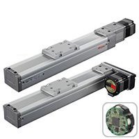
Electric linear slides like the EZS Series Linear Slides are designed to handle high moment loads and maintain precision under force:
- Move up to 60 kg (max transportable mass) and up to 800 mm/s
- High permissible moment loads support resistance to tightening forces and reduce deflection and positioning error
- Wide stroke options (50–850 mm) enable flexible machine design
If the load isn't centered on the moving carriage/table, then a moment load is created. The following image depicts a rolling moment load of 110 Nm, which can be easily handled by an EZS Series Linear Slide (max: 340 N·m). Moment load calculations are a critical part of our motor sizing process, and they should be a part of yours, too.

Additionally, a reversed motor configuration allows for a more compact footprint—ideal when space constraints are tight.
 |
 |
|
Engineering Tip When designing X-Y axes:
|
The Z-axis is responsible for bringing the screw head into contact with the screw and applying axial force during tightening.

Key Requirement: Controlled Torque Application
Applying the correct axial force ensures:
- Proper thread engagement
- Stable screw seating
- Reduced risk of stripping or damage
Recommended Solution: EAC Series Electric Cylinder
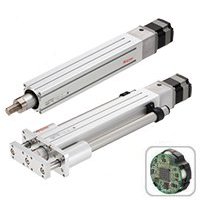
Electric cylinders such as the EAC Series are well-suited for this role:
- Up to 500 N of push force
- Up to 300 mm stroke
- Compact and slim design improves mechanical stability and reduces overhung load from Z-axis
 |
 |
Most importantly, they support push-motion control, which allows engineers to:
- Set a target pressing force
- Limit force through adjustable current and monitoring
This ensures every screw is pressed with consistent, controlled force throughout the cycle.
|
Engineering Tip The Z-axis not only needs to control its position but also its current for force control. Combining position and force control leads to more consistent fastening results. |
Screw Tightening Axis: Torque Control with a Motor
The final axis is responsible for actually tightening the screw with a set force, and this is where torque control becomes critical. Since we're already using the same technology on the other axes, why not use the same technology on the final axis?
Recommended Solution: αSTEP AZ Series Hybrid Step -Servo Motor
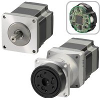
Closed-loop stepper motors like the αSTEP AZ Series Hybrid Step-Servo Motors offer built-in torque control features as well as a remote or software monitoring function:
- Torque limiting prevents over-tightening and protects against screw damage and material deformation
- Monitoring of position and load conditions for detection of abnormalities like screw galling or position errors
- Torque limiting output signals for communication with PLCs or HMIs
This effectively turns the system into a self-monitoring fastening station, reducing reliance on external sensors. Generally, an electric linear actuator offers more precision in controlled torque, better incremental position control, and higher repeatability than pneumatic or hydraulic linear actuators.
|
Engineering Tip Integrating torque control and diagnostics directly into the motor system simplifies system architecture. |
Here's the automated screw tightening system with its bill of materials.
 |
 |
Bill of Materials
| Description | Part Number | |
|---|---|---|
| Axis 1 | Electric Linear Slide - 200 mm stroke | EZSM6LE020AZAC |
  |
EtherNet/IP Compatible Driver | AZD-AEP |
| Connection Cable | CC050VZF | |
| DC Power Supply Cable | CC02D010-3 | |
| Axis 2 | Electric Linear Slide - 250 mm stroke | EZSM4E025AZAC |
 |
EtherNet/IP Compatible Driver | AZD-AEP |
| Flexible Connection Cable | CC050VZR | |
| DC Power Supply Cable | CC02D010-3 | |
| Axis 3 | Electric Cylinder with Brake - 500 mm stroke | EACM4RE05AZMC |
 |
EtherNet/IP Compatible Driver | AZD-AEP |
| Flexible Connection Cable | CC050VZRB | |
| DC Power Supply Cable | CC02D010-3 | |
| Axis 4 | αSTEP AZ Series Hybrid Step-Servo Motor - round shaft | AZM48A1C |
 |
EtherNet/IP Compatible Driver | AZD-AEP |
| Flexible Connection Cable | CC050VZR | |
| DC Power Supply Cable | CC02D010-3 | |
* All motor cables are 5 m in length.
* All DC power supply cables are 3 m in length.
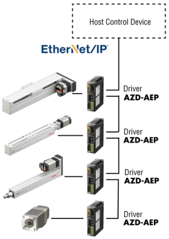
Smarter, Unified Control Across All Axes
All 4 axes of the screw tightening system use motors or linear actuators from the same αSTEP AZ Series Hybrid Step-Servo Product Family, which means they all share the same technology, universal drivers, and programming software. One of the biggest advantages of using a unified motor platform is standardization, and this makes it simpler and faster to add axes to the same machine.

Benefits of a Common Motor Platform
Using the same motor series across axes enables:
- Shared drivers and cables
- Simplified wiring
- Faster system startup and commissioning
Network-Based Control
With EtherNet/IP-compatible drivers, all axes can be controlled over a single network:
- Reduced cabling complexity (no I/Os to connect)
- Easier integration with PLC systems
- Scalable architecture for future expansion
Beyond basic motion, modern systems benefit from advanced capabilities that improve uptime and usability. All motors and linear/rotary actuators from the αSTEP AZ Series Hybrid Step-Servo Product Family are equipped with a battery-free absolute encoder that retains position data after power loss, eliminating homing routines and the need for external sensors. In addition, its built-in monitoring function enables tracking of system parameters such as load factor, position deviations, and operating cycles. By having this data available, engineers can implement predictive maintenance strategies to detect system wear early and reduce unplanned downtime.
|
Design Best Practices When designing a multi-axis screw tightening system, keep these tips in mind: Mechanical Design
Motion Control
Quality Assurance
|
Why Electrification is the Answer for Modern Screw Tightening Systems
A well-designed multi-axis screw tightening system combines rigid X‑Y positioning, controlled Z‑axis pressing, and precise torque control to achieve consistent fastening quality and minimize defects such as misalignment, galling, and over‑tightening.
Electric linear slides, electric cylinders, and closed-loop stepper motors provide a level of position, force, and torque control that is difficult to achieve with pneumatic or hydraulic actuators. In addition to repeatable motion and adjustable force profiles, electric actuators offer real-time feedback for built-in quality monitoring without the limitations of air or fluid-based systems.
As automation systems become more connected and data-driven, electric actuation already offers seamless integration with modern PLCs and popular industrial Ethernet networks to implement predictive maintenance strategies. For engineers, this means simpler control architectures, faster commissioning, easier troubleshooting, and lower long-term maintenance needs.
Oriental Motor offers various online support resources for the αSTEP AZ Series Hybrid Step-Servo Product Family, including a motor sizing tool, case studies, product videos, white papers, as well as downloadable 3D CADs, EDS files, and AOIs. For additional support, please contact our team.
Related articles:
Why Electric Actuators Are Better Than Pneumatic Actuators for Packaging Machinery
Pneumatic Actuators vs Electric Actuators: Which is Better?
Redefining Precision and Reliability for Wafer Pin Lifters
Benefits of an Absolute Rack and Pinion System Compared to Other Linear Motion Mechanisms
The Proper Way to Use a Gripper