Other than torque or speed, another factor should be considered when sizing motors.
| Have you ever watched the Olympics and wondered why figure skaters spin faster when they pull their arms inward instead of outward? The reason is load inertia. Pulling the arms inward reduces the body's load inertia, thus enabling a faster rotational speed. Load inertia affects motors in the same way. |  |
| What is "Inertia"? |
Inertia comes from the Latin word, iners, meaning idle or sluggish. Inertia is defined as the resistance of any physical object to any change in its speed. The bigger the inertia, the more resistant it will be to acceleration or deceleration.
| What is "Load Inertia"? |
Load inertia, or moment of inertia, is the resistance of any physical object to any change in its speed from the perspective of the rotational axis. For a rotary load, it's the product of its mass and the square of the perpendicular distance of the mass from the axis. Load inertia is typically referred to as "J".
High inertial loads require more torque to accelerate, so it's best not to exceed a motor's specifications, or the motor will stall.
| What is "Permissible Load Inertia" and "Inertia Ratio"? |
Manufacturers often offer permissible load inertia or an inertia ratio value for motors to help with motor sizing. Permissible load inertia values are guidelines typically given for AC and brushless motors (examples are given at the end of the post). Inertia ratios are typically given for stepper or servo motors, and they are calculated by dividing the total amount of load inertia (or reflected load inertia if geared) by the rotor inertia of the motor. If these values are exceeded, the motor may miss steps, stall, or vibrate. Closed-loop motors can handle a larger inertia ratio than open-loop motors.
Example: Recommended Permissible Inertia Ratios
| Motor Type | Frame Size (mm) | Frame Size (NEMA) | Inertia Ratio |
| Open-Loop Stepper Motors | 20, 28, 35 | 8, 11, 14 | 5:1 or less |
| Open-Loop Stepper Motors | 42, 50, 56.4, 60, 85 | 17, 20, 23, 24, 34 | 10:1 or less |
| Closed-Loop Stepper Motors | - | - | 30:1 or less |
| Servo Motors (Auto Tuning) | - | - | 50:1 or less |
| Servo Motors (Manual Tuning) | - | - | 100:1 or less |
| TIP: If you need to exceed the load inertia ratio... |
| Remember that this is a safe guideline and these values can be exceeded with the right setup. I remember talking to a customer who was building slot machines for casinos (the old kind with a lever). His team was using a stepper motor to spin the cylinders with the symbols that determined if you kept your day job or not. With a slower acceleration and deceleration ramp, they were able to reduce the required torque and use a motor outside of its permissible values...by a lot. |
| How to Calculate Load Inertia? |
Let's take a look at some common examples to see how the load inertia is calculated. First, the fundamental equation for inertia (J) is shown below.
Fundamental Inertia (J) Equation
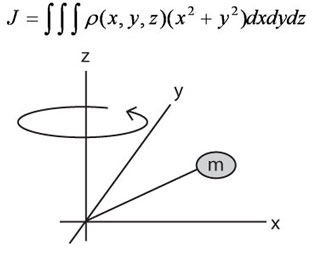
Don't worry. There are simplified forms of this formula. Five different simplified equations for five common loads (objects) are shown below for solid cylinder, hollow cylinder, rectangular object, rectangular object with off-center axis, and object in linear motion.
Choose the appropriate equation based on:
- Shape of load (object) in motion
- Rotational axis (x or y)
- Details provided (do you have the weight of the load?)
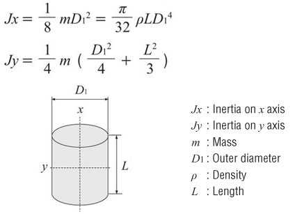
For example, if weight is provided, and you're calculating for a solid cylinder rotating about its x axis, use the first equation (Jx) below (with mass "m"). If the weight is not provided, but you have the diameter, thickness, and material density of the load, then the load inertia can be calculated with the second equation (Jx) below (with density "p").
Inertia of a Cylinder or Disc (as from the x or y axis)
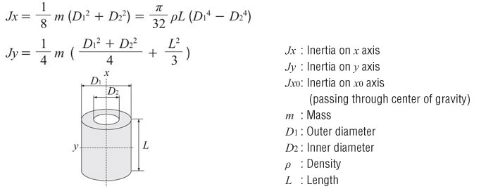
Inertia of a Hollow Cylinder (as from the x or y axis)
Inertia of a Rectangular Object (as from the x or y axis)
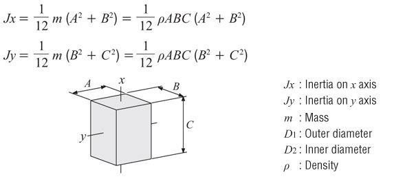
Inertia of a Rectangular Object with Off-Center Axis

Inertia of an Object in Linear Motion
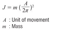
| Unit of Measure |
The units of inertia are commonly used in two ways, oz-in² and oz-in-sec². The former includes gravity, the latter only mass. Theoretically, inertia is a factor of mass so it should not include gravity, however, practically we can not easily measure mass on the earth.
Oriental Motor commonly provides inertia in oz-in². Then, when we calculate the acceleration torque, we divide the total inertia by gravity.
Gravity = 386 in/sec²
- oz-in² = Inertia based on weight
- oz-in-sec² = inertia based on mass
Conversion from oz-in² to oz-in-sec²

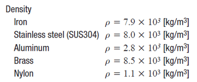
To complete these calculations, you may need some extra info such as material density to complete your calculations. This is necessary to calculate the weight of an object. More can be found with a simple online search.
| Example: Load Inertia Calculation |
Try to calculate the load inertia for the following application. Which parts do you need to calculate for?
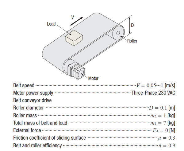
You'll need to add up all the load inertia values of all components driven by the motor. This includes the load, the belt, and the rollers. You'll need to use 2 different equations.
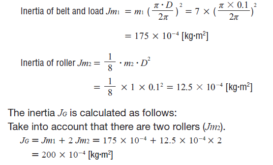
From what we've learned in  , here's the load torque calculation.

| Dealing with Large Load Inertia? Use a Geared Motor |
If you are dealing with a large amount of load inertia, there is a simple way to reduce it exponentially. The load inertia is reduced by the gear ratio squared. The resulting value is the reflected load inertia, which is the load inertia at the motor shaft (as opposed to load inertia at the gearhead shaft).

If you're interested in learning more, here's a white paper that discusses how to use gearheads to reduce load inertia. This is specifically for stepper motors.
| Where Can I Find "Permissible Load Inertia"? |
Now that you have calculated your total load inertia value, how do you find a motor that can handle it?
Here's an example of a permissible load inertia chart for a BLE2 Series 200/400 W brushless motor (from our catalog). Since we've already calculated the maximum permissible load inertia values for each gear ratio, you don't have to. Try not to exceed these values. The motors may still work if these values are exceeded, but it cannot be guaranteed.

If you don't have our catalog, we also list the permissible load inertia value on the website.

For stepper motors or servo motors, permissible load inertia values are not published, so please use recommended inertia ratio guidelines.
That's it for load inertia for now. Remember that load inertia is just one of three calculations necessary for a successful motor sizing (don't forget torque and speed). In the next Motor Sizing Basics post, I will explain how load inertia affects another component of torque - acceleration torque.
Need a refresher? Here's the motor sizing white paper (from the last post).
In the next post, I will explain how to calculate acceleration torque, RMS torque, and speed.
Here's the last post:
|
TIP: Is there an easier way to size motors? |
|
The thing to remember about motor sizing is that the result is only as good as the data. Make sure the values used for the calculation are as accurate as possible. The more guessing you do, the larger the safety factor you'll need to use at the end. Just like in the real world, there will be some unknowns. Example: Belt Conveyor |


