Now that we understand the calculations behind load torque and load inertia, we're a little closer to motor selection. You might be wondering why I separated load torque and acceleration torque calculations. That's because in order to calculate for acceleration torque, load inertia and speed must be calculated first.
|
TIP: Let's review first |
|
In In |

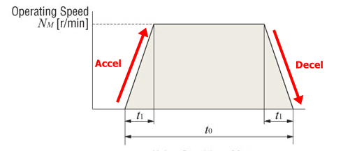
Here we show a typical motion profile with an acceleration, constant speed, and deceleration region.
- Start from zero speed
- Accelerate with t1
- Constant speed at Nm for a duration of t0-t1-t1
- Decelerate with t1
- Stop at zero speed
| Acceleration/Deceleration Torque |
As opposed to load torque (which is constant), acceleration torque is the required torque to accelerate an inertial load up to its target speed, or to decelerate from a set speed to zero. It is only present when accelerating (or decelerating) an inertial load, and it could be more or less than the load torque.
| Total Required Torque |
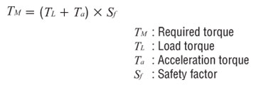
The total required torque is the sum of the load torque and acceleration torque as shown below (with a safety factor to cover for what we don't know).
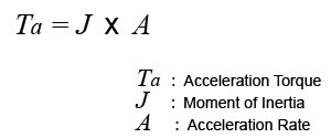
Mathematically, acceleration torque is made up of load inertia and acceleration rate as shown below. This is the most common equation used to calculate acceleration torque for all types of motors.
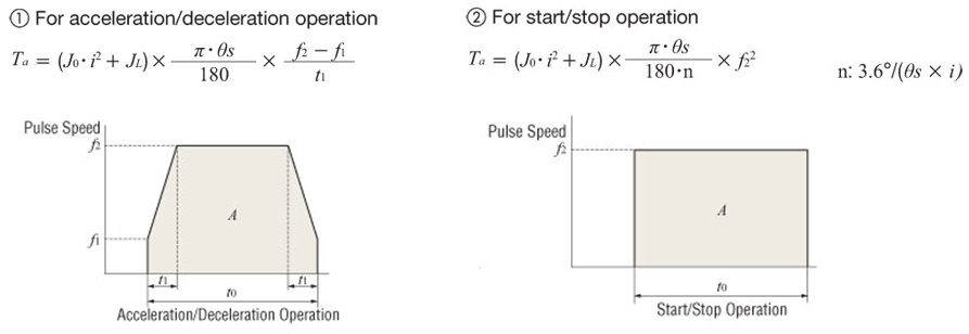
Stepper motors and servo motors can use a different formula since they deal with pulse speed (Hz). There are two equations available for 2 types of motion profiles: with or without acceleration/deceleration.
| Speed/RPM |
For a linear system, all linear units, such as required speed, need to be converted back to RPM or Hz in motor terms. The purpose of this is to determine (from the speed torque curve of the motor) if there is sufficient torque at that speed. These speed conversions are pretty basic, and you can figure out the formulas if you just use logic.
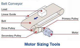
RPM on a rotary device is pretty straight forward. However, to convert from linear to rotary units, you'd have to convert with the right factor. For example, for belt and pulleys, use the pulley circumference. For ball screws, use the lead/pitch of the screw. For sprockets and chain, use the sprocket's pitch diameter or number of teeth. For rack and pinion, use the rack's pitch.
There are two main ways to calculate the required speed based on preference.
Here are some formulas that use "RPM", where PB is the pitch of the screw, VL is the linear speed, J0 is the rotor inertia, JL is the load inertia, and t1 is the acceleration time.
Required RPM (Nm):

Required Acceleration Torque (Ta):
Here are some formulas that use "Hz". Oriental Motor engineers typically use the pulse (Hz) formulas as shown below.
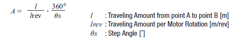
Number of Operating Pulses A
The number of operating pulses is expressed as the number of pulse signals that add up to the angle that the motor must rotate to get the load from point A to point B.
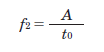
Operating Pulse Speed f2 (Hz)
The operating pulse speed can be obtained from the number of operating pulses, the positioning time, and the acceleration (deceleration) time.
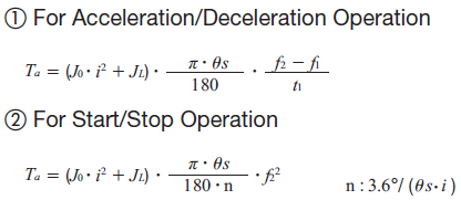
1) For Acceleration/Deceleration Operation
The level of acceleration (deceleration) time is an important point. The acceleration (deceleration) time cannot be set easily, because it correlates with the acceleration torque and acceleration/deceleration rates.
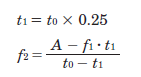
Initially, as a reference, calculate the acceleration (deceleration) time at roughly 25% of the positioning time. (The calculation must be adjusted before the final selection.)
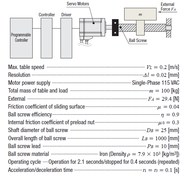
2) For Start/Stop Operation
|
TIP: Why use acceleration/deceleration at all? |
|
That's because even though immediately starting at the target speed might seem easier, but it results in a lot of acceleration torque, and thus requires a bigger motor. A bigger motor also equals higher cost and larger footprint, which are not the most desirable for machine designs. |
Here's a calculation example that you can follow along. I cannot mention how much these examples have helped me.
| Example: Calculation of Load Torque and Load Inertia |
In the following example, let's try to calculate load torque, load inertia, and acceleration torque using what we've learned so far. For me personally, I calculate load inertia first, then load torque, then speed, then acceleration torque. Information below describes the motor mechanism and given parameters.
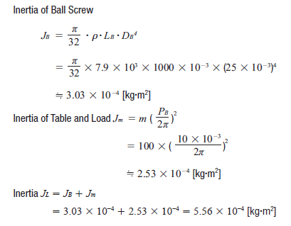
| Step 1: Load Inertia |
Calculate the load inertia for the screw, then the table and load separately, then add them up. The load inertia can be used for a tentative motor selection, which I will explain in a bit.
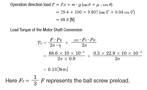
| Step 2: Load Torque |
Use the load torque equation for screws and fill in all the blanks for the variables. Make sure to use the right equation for the specific application.
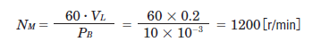
| Step 3: Speed (RPM) |
The required speed is calculated with the following equation. Use the pitch/lead of the screw PB in order to convert linear speed to RPM. In this case, we used an RPM formula rather than Hz.
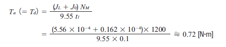
| Step 4: Acceleration Torque |
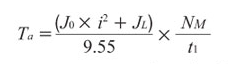
Here's a common formula for acceleration torque for all motors.
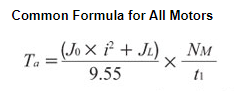
We just need to fill in the blanks for the variables. To calculate for acceleration torque Ta, tentatively select a motor based on load inertia (as mentioned previously), then plug the rotor inertia value J0 for that motor into the acceleration torque equation. We cannot calculate load inertia without rotor inertia from the motor.
|
TIP: How to tentatively select a motor based on load inertia |
|
For AC constant speed motors, AC speed control motors, and brushless speed control motors, you will need to look at the permissible load inertia values. For stepper motors or servo motors, you will need to know the allowable inertia ratio each type of motor can handle. For stepper motors, the general guideline is to keep the inertia ratio (load inertia or reflected load inertia divided by rotor inertia) under 10:1, and 5:1 for faster motion profiles or smaller frame sizes than NEMA 17. For closed-loop stepper motors, up to a 30:1 inertia ratio is recommended. For auto-tuned servo motors, the inertia ratio increases to 50:1. For manual-tuned servo motors, it can increase to 100:1. |
After you make a tentative motor selection based on load inertia, find the motor rotor inertia in the specifications, then plug the value for J0 in order to complete the acceleration torque calculation.
Just for kicks, here is another equation for acceleration torque using Hz units. "i" is for gear ratio.
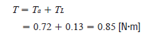
| Step 5: Total Required Torque and Safety Factor |
Add up the load torque and acceleration torque for total required torque. We will need a stepper motor that can output 0.85 Nm torque at the very least.
However, this is without a safety factor. If you use a safety factor of 2, then we will need a stepper motor that can output 1.7 Nm torque at about 1200 RPM; depending on the acceleration/deceleration rates. Safety factors are determined based on the accuracy of the variables.
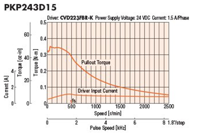
| TIP: Don't use maximum holding torque to size stepper motors |
|
For stepper motors, it's important not to use the "maximum holding torque" specification to select a motor since that is measured at zero speed and at full current. Since the torque produced by a stepper motor decreases as speed increases, you will need to look at the speed-torque curve to determine if the stepper motor will work at that speed or not. Typically, selecting a motor based on the total required torque and max required speed is a safe bet even though the motor may not need that torque at its max speed. A little bit of oversizing, when done properly, can extend life or improve performance of the motor.
|
| Step 6: RMS Torque (Servo Motors) |
For servo motors, there is another calculation that must be done, which is RMS torque. Root mean squared torque, or RMS torque, refers to an average value of torque that considers all the varying torque values used during operation as well as the time duration each torque value is needed. RMS torque is used to determine if the motor is properly sized to avoid thermal overload.
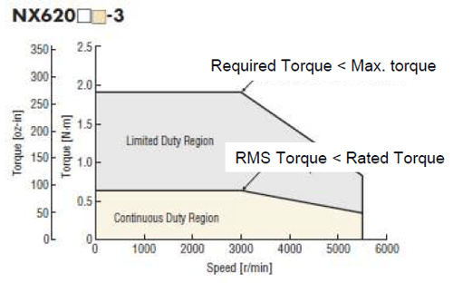
For servo motors, the required torque must be below the motor's peak torque, and the RMS torque must be below the motor's rated torque. Since peak torque requires a high level of motor current, it cannot be sustained continuously without overheating the motor.
Let's now look at the equation for RMS torque and visualize the variables in a motion profile pattern.
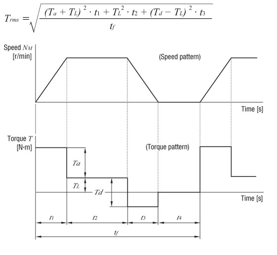
For this example, here's the calculation.
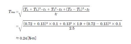
Here, t1 + t2 +t3 = 2.1 [s] from the operating cycle and t1 = t3= 0.1 for acceleration and deceleraion time. Therefore, t2 = 2.1-0.1 - 0.1 = 1.9 [s].
The ratio (effective load safety factor) of Trms and the rated torque of the servo motor TM is expressed by the formula below.
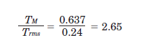
Generally, a motor can operate at an effective load safety factor of 1.5~2 or more.
| TIP: More about RMS torque |
For more information about RMS torque, here's a good article from Linear Motion Tips (Design World),  . . |
| Results |
For this application, we require a motor with high positioning (stop) accuracy, which would be either stepper motors or servo motors.
For a stepper motor, we would need to meet or exceed the following requirements.
Load Inertia = 5.56 × 10⁻⁴ [kg·m2]
Total Torque = 0.85 [N·m]*
Maximum Speed = 1200[r/min]
For a servo motor, we would need to meet or exceed the following requirements.
Load Inertia = 5.56 × 10⁻⁴ [kg·m2]
Total Torque = 0.85 [N·m]*
RMS Torque = 0.24[N·m]
Maximum Speed = 1200[r/min]
*Calculated torque does not include a safety factor.
With a torque, load inertia, and a speed value, we now have sufficient information for motor selection. However, there is another important criteria to consider in order to maintain long-term life. HINT: it has something to do with bearings. Please subscribe to receive new posts.
Here's a motor sizing guide (PDF) that you can download and keep with you.

In the next post, I will explain radial and axial loads.

Here's the last post.

|
TIP: Is there an easier way to size motors? |
|
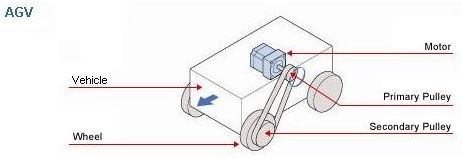
Use a motor sizing tool. FYI unit conversions are automatic with our motor sizing tools. Save your time for something else more important. Example: AGV
|