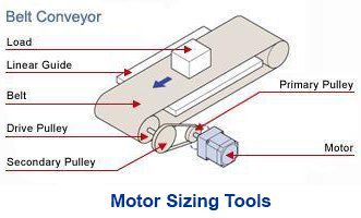
In the world of industrial robotics, there are several types of robots typically offering multiple axes of motion for tasks such as parts assembly, material handling, or pick and place operations. These include articulated robots, cartesian/gantry robots, SCARA robots, and Delta robots. Variations of end effectors such as grippers, welders or part rotators can be mounted on the end of the arm to perform different tasks. Depending on number of axes or load capacity, costs can easily add up. Limiting the operation range for these robotic axes of motion is an easy way to prevent costly problems or safety issues later.

Avoiding contact between a robotic arm and its surroundings may help prevent expensive product damage or even human injury while maintaining production uptime.
|
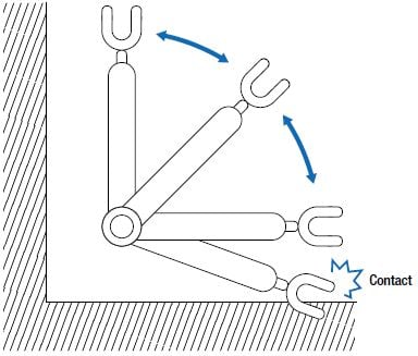
When dealing with range of motion within a confined space, it may be difficult to avoid hitting something with a robotic arm especially without complex algorithms and vision sensors. Depending on factors such as force or speed, this could mean an injury to a human operator, or product damage, both of which increases production cost as well as decrease production efficiency. To counter this problem, exteranl limit sensors must be used in order to limit the operation range of motors. These require additional space, expertise, inventory and wiring. |
 |


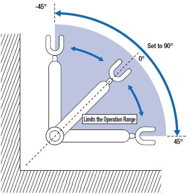
Use the software limit parameters in a motor and drive system to prevent motor operation in restricted regions in the form of step count, degrees or mm. You can also control how the motor stops.

|
Many motor systems (servo, stepper) used for controlling these axes of motion typically offer software limits that can serve the same purpose of external limit sensors. When software limits are set and stored within the driver or controller, the motor will only operate within a safe region where it won't be able to cause an injury or damage. This parameter is typically included in the software of many motor and drive systems. However, many machine designers still use a combination of limit sensors, encoders and/or software limits for multi-layered protection. When an absolute encoder is used, external sensors can be eliminated, but additional hardware, such as a battery, is necessary to retain position information. |
 |
|
When software limits are used with a Related Post: To help explain the benefits of sensorless, absolute positioning, we've built a few robotic demos using AZ Series absolute stepper motors without external homing or limit sensors. Please watch these videos below or keep an eye out for these demos at our upcoming
|


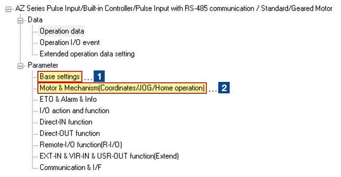
For Oriental Motor's  motors and actuators, software limits parameters can be found in both the BASE SETTINGS and MOTOR & MECHANISM (COORDINATES/JOG/HOME OPERATION) tabbed windows within the
  .
.
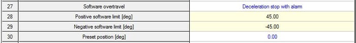
Please see the screenshot example below to locate these parameters in the MEXE02 support software. The parameters below would allow a robotic arm (pictured above), which has a home position of 45 degrees from a horizontal position (0 position), to travel 45 degrees in either direction. If the motor travels into the set limits outside of the +45 or -45 degree limits, then the motor will decelerate to a stop, and then an alarm will be generated by its driver.
Instructions:
- In the MEXE02 software window, click on BASE SETTINGS under PARAMETER. This is in the top left corner. Refer to 1st image below. Make sure that you units are set to "deg".
- Enter "45.00" for POSITIVE SOFTWARE LIMIT on line 28.
- Enter "-45.00" for NEGATIVE SOFTWARE LIMIT on line 29.
- Click on MOTOR & MECHANISM right under BASE SETTINGS under PARAMETER.
- Make sure that "PRIORITIZE ABZO SETTING" is selected in INITIAL COORDINATE GENERATION & WRAP COORDINATE SETTING on line 11.


That's it. Oh one more thing. Remember to write the data into the driver in order to save these parameters. This is pretty important unless you want to repeat this all over again.