AC motors are simple to control, rugged, and cost effective for general purpose applications. These reasons are why they are the most popular type of electric motor across various industries. In this post, we will briefly introduce induction motors and demonstrate how to operate these motors.
A Little History
The term "induction" in induction motors (also known as asynchronous motors) refers to electromagnetic induction, which is the principle theory of operation for induction motors. I will explain that in the next section. According to Wikipedia, there are a few names that are tied to the invention of the AC induction motor. In 1824, the French physicist, François Arago, discovered rotating magnetic fields and coined the term, Arago's Rotations (or Arago's Disc). In 1831, Michael Faraday was able to explain the effects by introducing the theory of electromagnetic induction. In 1879, the first primitive induction motor was demonstrated by Walter Baily by manually turning switches on and off. The first AC commutator-free three-phase induction motors were independently invented by Galileo Ferraris in 1885 and Nikola Tesla in 1887. Both published papers in 1888 to explain these technologies. Tesla applied for US patents in 1887 and was granted some of these patents in 1888. George Westinghouse, who was developing an alternating current power system at the time, licensed Tesla's patents in 1888 and purchased a US patent option on Ferraris' induction motor concept to develop the technology further. General Electric (GE) began developing three-phase induction motors in 1891. By 1896, General Electric and Westinghouse signed a cross-licensing agreement for the bar-winding-rotor design, later called the squirrel-cage rotor. The same concept is still being used today.
|
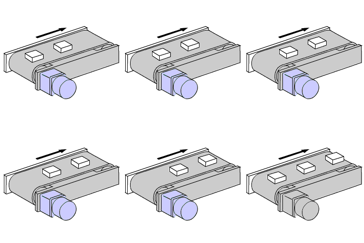
Induction motors are ideal for applications that require continuous operation in one direction, such as conveyors, mixers, and rotating signs. They are rated for continuous duty and typically last a long time due to its simple structure. |
 |
Design & Operating Theory
 |
This image shows the structure of an AC induction motor, which is the most basic type of AC permanent split capacitor motors. The rotating element, the rotor, is supported in the motor case by 2 ball bearings for long life. The stator is located around the rotor with a thin air gap. The output shaft is connected to the rotor. The lead wires are connected to the stator windings. The flange bracket is pressed fit into the motor case to ensure quality. |
As alternative current is supplied to the copper windings in the stator, a rotating magnetic field is generated around the rotor at the speed of the AC oscillations. By Fleming's left-hand rule, the moving magnetic field induces a current on the aluminum bars (conductor) in the steel rotor, which generates its own opposing magnetic fields (Lenz's Law). The magnetic fields from the rotor then interacts with the rotating magnetic field from the stator, and the rotor begins to rotate.
Single-Phase Induction Motors
Single-phase induction motors are offered in different voltages and frequencies for different regions of the world. For the USA, single-phase motors are typically offered in 110/115 volts or 220/230 volts, which are easily accessible. 60 Hz is the typical power supply frequency.
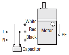
Here are the actual wiring diagrams for these standard 3-wire motors. FYI the rotation direction of the motor is indicated when viewed from the output shaft side of the motor.

While the theory of operation should be the same with all single-phase permanent split capacitor type AC motors in the market, the lead wire colors could be different for different manufacturers.
For a standard 3-wire motor, the lead wire colors are typically white, red, and black. Black is always connected to neutral (N). Both white and black are connected to the 2 terminals of the dedicated capacitor. When the live (L) is connected to either the black or red via the capacitor terminal, the motor will start rotating in the intended direction. For the terminal box type motors, the theory of operation is the same. However, the terminals are labelled Z2, U2, and U1.
Wiring the Capacitor
For single-phase motors, the capacitor is critical to its start-up operation. Without the starting torque provided by the capacitor, you would have to help start the motor by manually rotating the shaft. This is kind of like the old propellers on a vintage airplane. Make sure you don't forget to properly wire the capacitor. This was a very common troubleshooting case from my days as a tech support engineer.
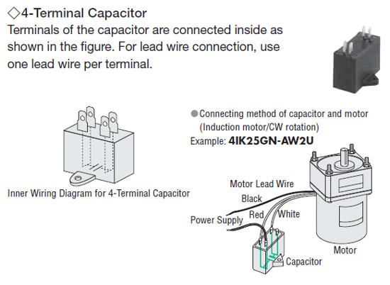
Here's a wiring example of a 4-terminal type capacitor and a single-phase motor.
| Don't be confused by the number of terminals on the capacitor. The inner wiring diagram below shows that the two closest terminals are internally connected. Electrically, this is the same as the traditional two-terminal type capacitors, which offer only one terminal on each side. |  |
We also produced a video to demonstrate the proper way to wire these motors, including circuit breakers, switches, and capacitor.
Three-Phase Induction Motors
Three-phase induction motors are typically offered in 220/230 volts and 50/60 Hz in the USA. In some cases, 460 volts is offered. Three-phase motors can either run at constant speed or with an inverter/VFD (variable frequency drive) for variable speed applications.
Here are the actual wiring diagrams for these standard 3-wire motors. FYI the rotation direction of the motor is indicated when viewed from the output shaft side of the motor.

For a 3-wire three-phase motor, we have the same wire colors. The 3 phases from the power supply are labelled L1 (R), L2 (S), and L3 (T). Connect red to L1 (R), white to L2 (S), and black to L3 (T). For the terminal box type motors, the terminals are labelled U, V, and W. The theory of operation is the same. To switch rotation direction, switch any of the 2 connections between R, S and T.
When there's an overload or locked shaft condition, either an electromagnetic switch or an inverter's electronic thermal function is recommended to prevent motor burnout.
You probably noticed that there is no capacitor in the wiring diagram. With single-phase motors, a capacitor is required to generate a poly-phase power supply. With three-phase motors, a capacitor is not necessary. We also produced a video to demonstrate the proper wiring.
| Last, but not least. Don't forget to electrically ground the motors with its dedicated protective earth grounding terminal (PE) to avoid shock or injury by personnel. |  |
That's all folks for single-phase and three-phase induction motor wiring. Stay tuned for the next post where I will explain wiring for other types of AC motors, such as reversible and electromagnetic brake motors.
Remember to subscribe!
|
A little more history... Here's a video that briefly explains the history of development of Oriental Motor's AC motors from 1966, when the K Series was considered the de facto standard of all AC motors, to the introduction of KII Series and KIIS Series. |


