AC motors have the same operating theory, but by changing its design a little, you can modify its characteristics to suit certain applications better. In the last post, I focused on AC induction motors for unidirectional applications. In this post, I will explain what makes AC reversible motors and AC electromagnetic brake motors ideal for start/stop, reversing, or vertical applications, and demonstrate how to operate them.
Reversible Motors
First, let's understand why reversible motors are called reversible motors to clear up any confusion. All permanent split capacitor type AC motors are reversible. However, induction motors cannot reverse direction instantaneously since they need to come to a complete stop first. Reversible motors can reverse direction much faster. For example, induction motors can be reversed by switching its lead wires, but since it has about a 30 revolution overrun compared to a 5 revolution overrun offered by the reversible motors, they are not the most ideal type of motor to use if instant reversing is necessary.
The overrun is calculated by measuring the number of motor shaft revolutions it takes for the motor to stop once power is removed. Newton's First Law of Motion says that an object at rest stays at rest, and an object in motion stays in motion; unless some external force is applied, such as friction. Compared to a reversible motor with brake friction, the only components producing friction inside an induction motor are the ball bearings, therefore the overrun is much longer for induction motors.
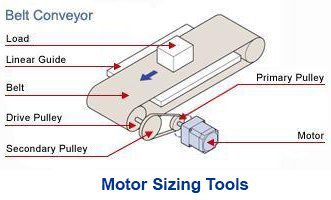
| Reversible motors are ideal for start/stop or reversing applications that require shorter overrun than induction motors, such as reversing conveyors. They generate more heat, so a 50% duty cycle is recommended (with a maximum of 30 minutes of continuous operation). |  |
Design Comparison to Induction Motors
| Structure of Induction Motors | Structure of Reversible Motors |
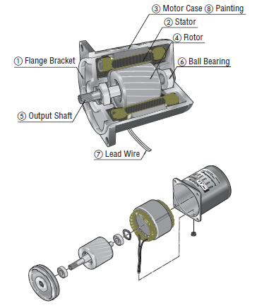 |
Same as induction motors except for additional friction brake components listed below:
|
The main design difference between an induction motor and a reversible motor is the addition of a friction brake (depicted above), which allow reversible motors to drastically reduce overrun and perform start/stop and reversing operations. A spring continuously presses the friction brake against an armature and decreases the motor overrun when commanded to stop. The holding torque produced by the friction brake is only about 10% of the motor's output torque. This torque can be increased by the gear ratio, but it's designed to reduce overrun; not to hold a load vertically.
Another design difference is the utilization of a balanced winding. This means that the primary winding and secondary winding have the same resistance and inductance. This allows equal torque regardless of which phase is energized, or which direction the motor is rotating. Coupled with the friction brake, these 2 features allow direction change on the fly.
| Since the friction brake is constantly rubbing against the armature, we use a capacitor that's rated higher than the ones used by induction motors to increase starting torque for starting and reversing. Due to increased operating temperature, we also derate the duty cycle to 50% (50% on, 50% off). However, as long as you can keep the motor case temperature at below 100° C, the motor will last. |  |
Theory of Operation
As power is supplied to the copper windings in the stator, a rotating magnetic field is generated around the rotor at the speed of the AC oscillations. By Fleming's left-hand rule, the moving magnetic field induces a current on the aluminum bars (conductor) in the steel rotor, which generates its own opposing magnetic fields (Lenz's Law). The magnetic fields from the rotor then interacts with the rotating magnetic field from the stator, and the rotor begins to rotate.
|
Want to know more about operational theory of AC motors?
|

Wiring
Here is the wiring diagram for single-phase reversible motors (same as single-phase induction motors). Since three-phase motors are often used with inverters, or VFDs, for continuous duty speed control, a three-phase reversible motor is not common. FYI the rotation direction of the motor is indicated when viewed from the output shaft side of the motor.
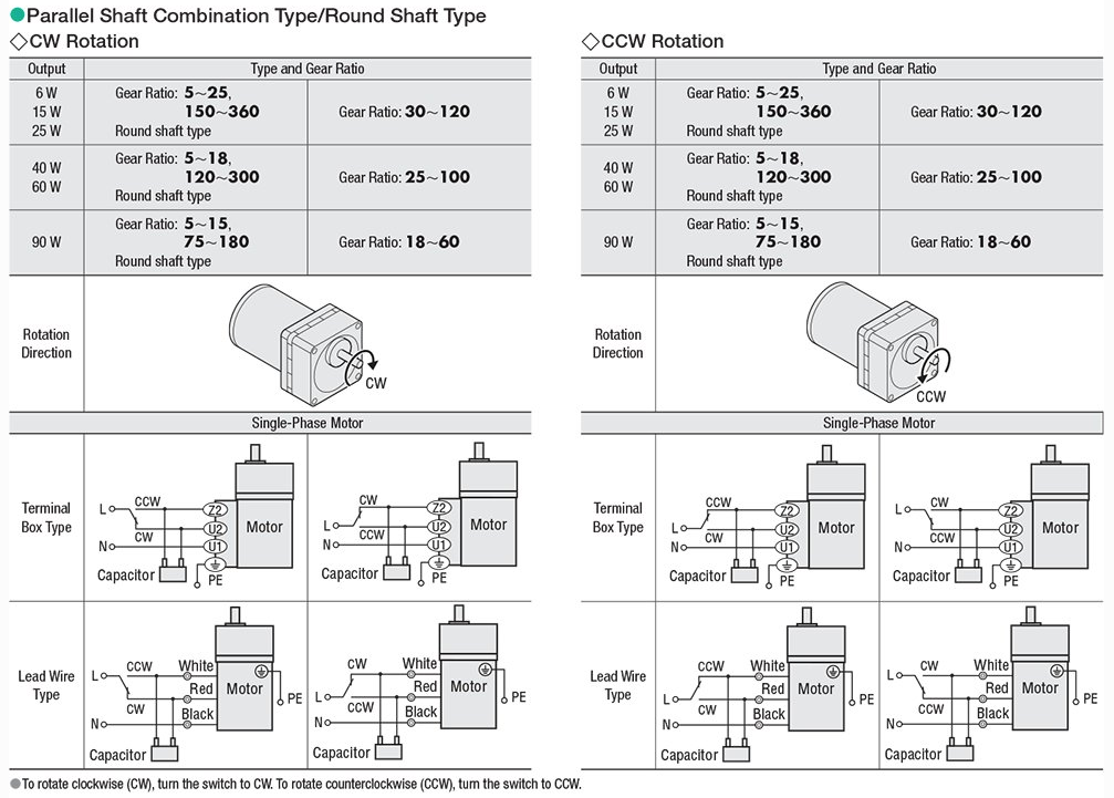
While the theory of operation should be the same with all single-phase permanent split capacitor type AC motors in the market, the lead wire colors could be different.
For a standard 3-wire motor, the lead wire colors are white, red, and black. Black is always connected to neutral (N). Both white and black are connected to the 2 terminals of the dedicated capacitor. When the live (L) is connected to either the black or red via the capacitor terminal, the motor will start rotating in the intended direction. For the terminal box type motors, the theory of operation is the same. However, the terminals are labelled Z2, U2, and U1.
The Capacitor
For single-phase motors, the capacitor is critical to its start-up operation. Without the starting torque provided by the capacitor, you will have to help start the motor by manually rotating the shaft. This is kind of like the old propellers on a vintage airplane. Make sure you don't forget to properly wire the capacitor. This was a very common troubleshooting case from my days as a tech support engineer.
Here's a wiring example of a 4-terminal type capacitor and a single-phase motor.
| Don't be confused by the number of terminals on the capacitor. The inner wiring diagram below shows that the two closest terminals are internally connected. Electrically, this is the same as the traditional two-terminal type capacitors, which offer only one terminal on each side. | 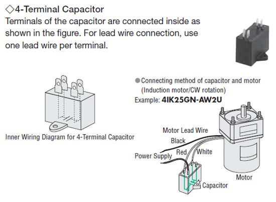 |
| As with all motors, don't forget to electrically ground the motors with its dedicated protective earth grounding terminal (PE) to avoid shock or injury by personnel. | 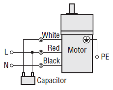 |
Here's a demonstration video to show you what the standard wiring looks like.

Electromagnetic Brake Motors
Similar to a reversible motor, an electromagnetic brake motor is a reversible motor with a power-off-activated electromagnetic brake attached. Since the base motor is a reversible motor, duty cycle is the same at 50% (with a maximum of 30 minutes of continuous operation). The difference is that electromagnetic brake motors offer shorter overrun and more holding torque.
| Electromagnetic brake motors are designed for vertical applications, such as load elevators. The power-off-activated electromagnetic brake produces close to the motor's rated torque and helps keep the load safe (and any personnel) if the power fails during operation. |  |
The electromagnetic brake is designed to lock the motor shaft in order to hold a load in place. It also reduces the overrun from 30 revolutions to about 2 revolutions. For start/stop applications, maximum operating cycle of the electromagnetic brake is 50 cycles/minute or less. For higher operating cycles, either a brake pack, clutch and brake type motor, or high efficiency stepper motors are recommended.
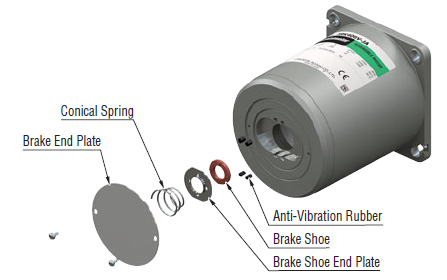
| The electromagnetic brake uses the same voltage as the motor and is designed to engage/lock the load in place. When the magnet coil is energized, it becomes an electromagnet and attracts the armature against the force of the spring, thereby releasing the brake and allowing the motor shaft to rotate freely. When the magnet coil is not energized, the spring presses the armature onto the brake hub and holds the motor shaft in place. | 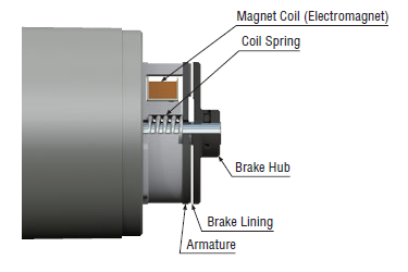 |
Compared to induction and reversible motors, the wiring method for electromagnetic brake motors is a little more complex since more components are involved. A capacitor is also required for single-phase electromagnetic brake motors. A three-phase electromagnetic brake motor is offered for variable speed applications; due to the base motor being a continuous duty rated induction motor instead of a duty limited reversible motor.

If you follow the wiring diagram above and use the switches specified, the electromagnetic brake will automatically engage when the motor stops, and disengage when the motor runs. The SW1 switch controls both the motor power and the brake power, and the SW2 switch controls the motor direction.
Here's a demonstration video to show you what the proper wiring looks like, including circuit breakers, switches, and CR circuit modules (for surge suppression).
Overrun, Duty Cycle Comparison
Here's a summary of the main differences between induction motors, reversible motors, and electromagnetic brake motors.
| Type of Motor | Overrun | Duty Cycle |
| Induction Motor | 30~40 revolutions | Continuous |
| Reversible Motors | 5~6 revolutions | 50% |
| Electromagnetic Brake Motors | 2~3 revolutions | 50% |
The overrun value is for the motor shaft. Adding a gearhead with a high gear ratio, increasing friction, or reducing load inertia are all methods that help in reducing the overrun.
The duty cycles above are recommended values. As a general rule, as long as you keep the motor case temperature below 100° C, the motor will be fine.
That's it for AC reversible motors and AC electromagnetic brake motors. Stay tuned for a post about torque-speed characteristics of AC motors, and remember to subscribe!
|
Learn more about KII & KIIS Series Here's a video that briefly explains the KII & KIIS Series AC induction motors, AC reversible motors, and AC electromagnetic brake motors as well as their intended applications. |