There are three main types of stepper motors available in the market: PM (permanent magnet) type, VR (variable reluctance) type, and hybrid type. What are the differences, which one should you use, and how do they work?
Let's quickly review what a stepper motor does. Stepper motors rotate in specific increments of "steps" without encoder feedback or complicated PID loops. Rotation amount and speed are easily controlled by the number of pulses and frequency, and a stepper motor offers highly repeatable stop accuracy at ±3 arc minutes (±0.05°). Holding torque is generated without an electromagnetic brake when a stepper motor is powered but at standstill. They are ideal for cost-sensitive applications where motors need to stop accurately and provide holding torque.
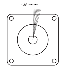
The design of a stepper motor affects its characteristics. In the next few minutes, I will introduce the three types of stepper motors in the market and why one is preferred over the others.
PM "Permanent Magnet" Type
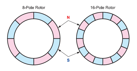
This is a stepper motor whose rotor is made from two permanent magnet rotors that are slightly offset from each other. The permanent magnet is axially magnetized; meaning that the north and south poles alternate and are on the same axis as the motor shaft. When current is applied to windings, poles on the stator are magnetized and align with the opposite poles from the permanent magnet rotor. For example, north poles would align directly across from south poles.
A widely used PM type stepper motor is the 2-phase claw type as shown below.
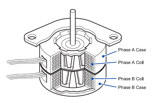
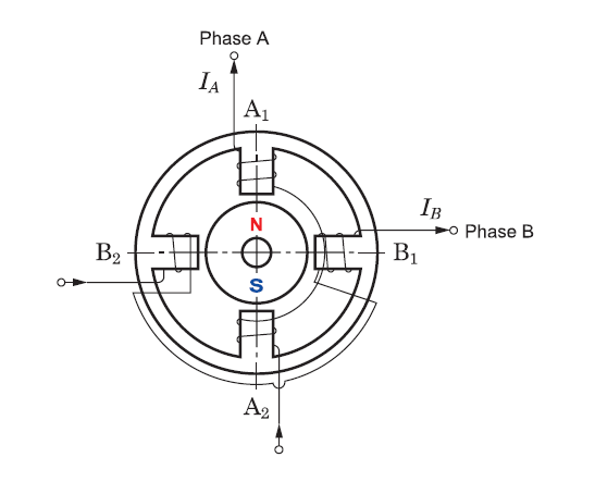
The image below shows a rotor and a stator in which a current is applied so that the A1 pole is magnetized to the south pole and the A2 pole is magnetized to the north pole, therefore attracting the opposite poles from the rotor's permanent magnets. If the current is switched from phase A to phase B to magnetize B1 to the south pole and B2 to the north pole, the rotor would rotate by 90° in the clockwise direction.
The step angle is represented as follows using the number of poles of the rotor (Np) and the number of phases (Nphase). If the number of poles or phases increases, the step angle decreases. However, as the number of poles increases, the magnetic force and torque also become weaker.
 |
 |
A PM type stepper motor is simple in construction and inexpensive to manufacture. The permanent magnets allow PM type stepper motors to output higher torque. However, high-speed performance is limited due to a large loss during rotation. A PM type stepper motor is often used for simple positioning since its resolution tends to be larger than other types (ie, 3.6° or bigger). For higher resolution, half-stepping or microstepping is recommended. With microstepping, the driver's ability to control current precisely at each phase becomes increasingly important in determining the motor's repetitive position accuracy. Another difference is that PM type stepper motors use constant voltage drivers, which are more difficult to use than constant current chopper drivers.
VR "Variable Reluctance" Type
This is a stepper motor that features teeth on both the rotor and stator, where the magnetic forces are concentrated. It offers the simplest design out of the three types discussed here. The image below shows a 3-phase VR type stepper motor with 8 poles and 12 slots. A ferromagnetic material, such as iron, is used for most magnetic cores because of its abundance on earth and its ability to pass magnetic flux easily. A VR type stepper motor has no magnets, which means it cannot output holding torque or detent torque at standstill.
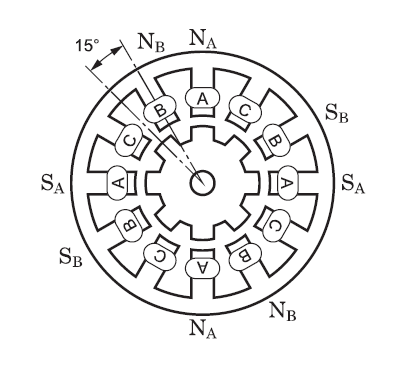
The image below shows an example of a 4-pole, 6-slot VR type stepper motor. The "teeth" on the rotor are attracted to the magnetized poles on the stator. The stator poles on each side of the rotor is magnetized north and south by winding the poles in reverse.
In the images below, we show a "Phase B excited" state on the left. In this condition, the closest teeth from the rotor will align themselves to the nearest magnetic pole on the stator. The rotor will rotate counterclockwise 30° until the teeth are aligned across each other (see "Stop position of phase B"). Now, when phase C is excited in the same way, the rotor will rotate 60° until the teeth are aligned with phase C.
| Phase B excited | Stop position of phase B | Stop Position of phase C |
 |
||
An advantage of the VR type stepper motor is that there is no need to change the polarity of the stator poles, so that its drive circuitry can be simplified. Its disadvantage is its inability to fine-tune torque control since torque is proportional to the square of the current instead of to the current. However, since it does not use permanent magnets, its high speed performance is better than a PM type stepper motor.
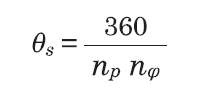
The step angle of the VR type stepper motor is represented in the following formula. Np is the number of teeth of a rotor, and Nphase is the number of phases. For finer resolutions, it's effective to increase of the number of teeth of the rotor. However, if the number of stator slots is also increased, the structure becomes very complicated to manufacture. The image below shows a 50-tooth rotor and stator design. This is a 4-phase stepper motor where the coil is divided into 4 sets. Inputting Np = 50 and Nphase = 4 would result in a step angle of 1.8°.
 |
|
VR type stepper motors have been around for a long time. These motors have less torque drop-off at higher motor speeds, so they are often a better choice than PM type stepper motors in mid to high speed applications. However, they are known to produce more noise, so their application range is limited. VR type stepper motors are less common than PM type stepper motors in the market.
Hybrid Type Stepper Motor
A "hybrid" type stepper motor combines the design and advantages from both permanent magnet type and variable reluctance type stepper motors. Therefore, a hybrid type stepper motor uses both the permanent magnet rotor as well as a toothed rotor and stator in its design. With strong permanent magnets, a toothed rotor, a toothed stator, and a tiny air gap, a hybrid-type stepper motor is able to focus the magnetic flux better than the other two types. Low loss is achieved by stacking magnetic steel laminations that can easily pass the magnetic flux.
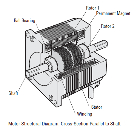
The construction of a hybrid type stepper motor starts with two rotor cups (Rotor 1 and Rotor 2) and a strong rare earth permanent magnet, which is axially magnetized. Two ball bearings mount the rotor into the motor casing. There are either 50 teeth (1.8° per step) or 100 teeth (0.9° per step) on the rotors. One rotor is magnetized as the north pole, and one rotor is magnetized as the south pole. Each tooth on the rotor cups becomes a magnetic pole.
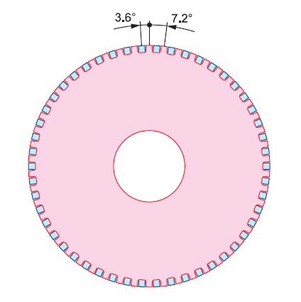
In the 2 images below, we show a top-down view of the two rotors; starting with the north pole rotor on top. The two rotor cups are in different colors. Red is the north pole rotor, and blue is the south pole rotor.
|
|
|
Since there are 50 teeth, the full pitch is 7.2°. The two rotor cups are offset by a half pitch (3.6°) so the south pole teeth from rotor 1 line up in between the north pole teeth from rotor 2. From a cross-sectional view of the rotor, you can clearly see that the north and south pole teeth are alternating because of the offset of the two rotor cups. When the windings are energized or excited by the driver, the stator poles turn into electromagnets, and the permanent magnet rotor follows them by both a pull and push effect and stops at fixed increments. The north poles from the stator will attract the south poles from the rotor, and vice versa.
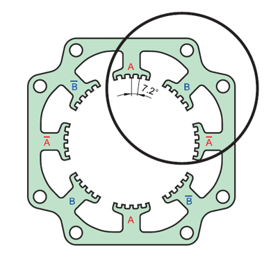
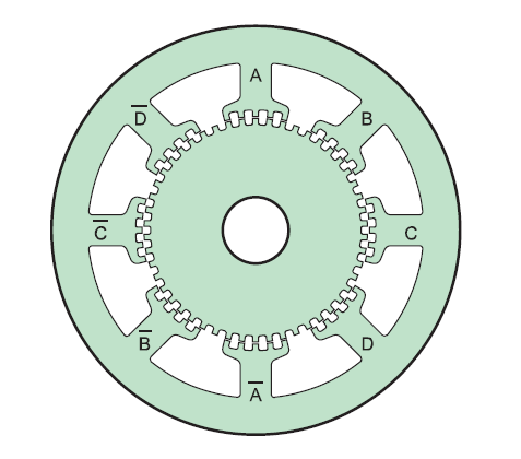
There are eight stator poles in the stator. When windings are wound to the main poles and a current is applied, each pole is magnetized to the north pole or the south pole. The direction of the current can determine the magnetic polarity. When excited, two poles at opposite sides have the same polarity, and two poles positioned at 90° from these poles have the opposite polarity. The main poles excited together are called "phases" and can be divided into two phases (phase A and phase B). This is why it's called a "two-phase" stepper motor.
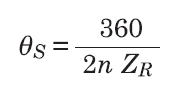
The step angle of a hybrid type stepper motor is in inverse proportion to the number of small teeth on the rotor ZR and the number of phases n. The denominator 2 indicates that the main poles of the stator can be configured into two states, the north pole and the south pole. This is a fundamental design difference between VR type and hybrid type stepper motors.
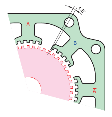
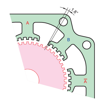
| Teeth Arrangement Offset | Phase A Excited | Phase B Excited |
 |
 |
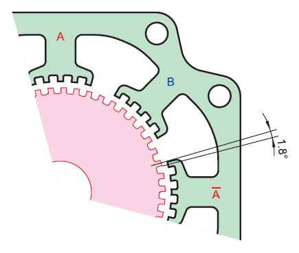 |
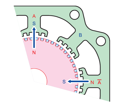
The reason why hybrid type stepper motors rotate 1.8° per step is that the motor only moves a quarter of a tooth pitch per step due to the geometric design between the rotor and stator. When phase A is excited as the south pole and its stator teeth are directly aligned with the north pole teeth from the rotor, the stator teeth of phase B are actually offset from the teeth of the rotor by 1.8°. This is called the teeth arrangement offset and is the reason why a two-phase hybrid type stepper motor rotates 1.8 ° per step.
For a 0.9° per step stepper motor, both the rotor teeth need to increase to 100. Anything more than 100 teeth is quite difficult to manufacture.
With hybrid type stepper motors, high torque can be obtained by the rare earth permanent magnets while high resolution obtained by the small teeth is maintained. Also, the relationship between current and torque is close to proportional; making it easier to control than a VR type stepper motor. Hybrid type stepper motors can also achieve higher resolution (ie: 0.72° per full step / 500 steps per revolution). Even higher resolutions can be achieved by microstepping.
Summary
- PM (Permanent Magnet) Type: uses permanent magnets, moderate torque, low to mid-speed
- VR (Variable Reluctance) Type: toothed rotor/stator, low torque, mid to high speed
- Hybrid Type: combines permanent magnets and teeth, good combination of torque and speed
The most popular stepper motors in the market are the hybrid type, as they offer the best performance, albeit at a higher cost. Hybrid stepper motors will work well for most applications while permanent magnet or variable reluctance stepper motors are limited to certain applications. Stepper motor drivers are becoming increasingly smarter in recent years due to their technological improvements in functions, distributed control, and ease of programming. Gearheads and closed-loop feedback can be added to a stepper motor system to enhance performance and expand its range of applications. Working with a manufacturer that can provide all the necessary components and training can make life easier.
Interested in learning more?
Learn more about stepper motor fundamentals and product technologies from our technical articles and white papers.
Please meet our high torque hybrid stepper motors!
