This is part 2 of the Technical Manual Series for brushless motors, which explains the structure and operating principles for brushed motors for comparison. We will explain brushless motors next.
Before explaining the brushless motor operating principle, let us first introduce the structure and rotation principles for the DC motor, the precursor of the brushless motor. DC motor is an abbreviation for direct-current motor, and as the name implies, it is a motor that rotates by applying a direct-current voltage.
Brushed DC Motor Structure and Principles
| 2.1 DC Motor Structure and Rotation Principles |
2.1.1 Brushed DC Motor Structure
The general structure of a DC (brushed) motor is shown in Fig. 2.1.
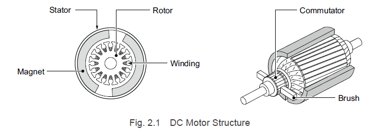
Permanent magnets are located within the stator, and situated in the center of these is a rotor containing windings. The rotor contains several windings, and both ends are connected to the commutator. Current flows through the windings via the commutator that is in contact with the brushes. The structure is such that rotation of the rotor switches the commutator segments coming into contact with brushes, and the windings through which the current flows switch over sequentially as well, continuing the rotation.
2.1.2 Brushed DC Motor Rotation Princicples
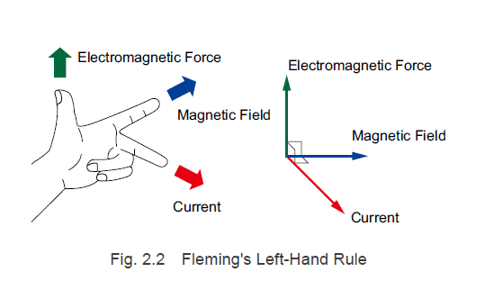
We will now explain the rotation principles for DC motors using Fleming’s left-hand rule shown in Fig.
2.2 and the simplified model shown in Fig. 2.3.
Making a current flow through a conductor placed within a magnetic field causes the conductor to receive a force (electromagnetic force). According to Fleming's left-hand rule, the orientations of the magnetic field, current, and electromagnetic force are related orthogonally to one another. The electromagnetic force generated in this condition is proportional to the magnetic field strength, permeability, and current value.
Permeability μ is a coefficient that represents the ease with which a substance can be magnetized, and the product of the magnetic field strength H and the permeability μ is called the magnetic flux density B.
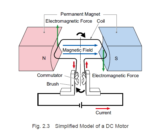
In the simplified model shown in Fig. 2.3, a pair of permanent magnets is arranged such that the north and south poles face each other. A single coil winding is located between the permanent magnets, and the structure allows for it to rotate freely around the dashed-dotted line. Both ends of the coil are connected to the commutator, which is in contact with the brushes. The brushes are wired to a DC power supply, and current is supplied from the positive side, which passes through the coil and
returns to the negative side.
For the explanation of the motor’s rotation principles, let us assume that the orientation of the windings shown in Fig. 2.3 is the initial point (0°).
1. A current i flows through the brushes and commutator to the coil inside of the magnetic
field.
2. According to Fleming's left-hand rule, the electromagnetic force F moves upward in the conductor on the north pole side and downward in the conductor on the south pole side, and the coil rotates clockwise.
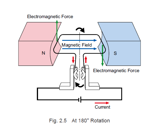
3. When the coil rotates and approaches 90°, as shown in Fig. 2.4, the commutator and brushes are no longer in contact, and the current cannot flow. While the current may not be flowing, the coil rotates via the force of inertia.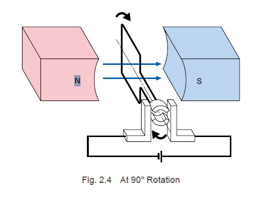 4. When the coil rotates via the force of inertia, the commutator and brushes make contact again, causing the current to flow and electromagnetic force to be generated. When it rotates to the 180° position shown in Fig. 2.5, it enters the same state that is shown in Fig. 2.3.
As stated above, the brushes and the commutator segments that are in contact with them switch places, which switches the direction of the current that flows through the coil, creating an electromagnetic force in the coil that moves in one direction. This allows the DC motor to continue rotating. The act of changing the direction of the current flowing through the coil is called commutation.
| TIP: Motor Torque |
|
The electromagnetic force F generated in the conductor, the magnetic flux density B, and the current i are related as follows.
|
2.1.3 Brushed DC Motor Characteristics
The DC motor speed-torque characteristics are shown in Fig. 2.6. The highest speed is achieved at the no-load state (in which no load is being applied to the shaft), and as the load torque increases, the
rotation speed decreases. When the motor speed is zero (with the shaft in a fixed state), stall torque is
generated.
This feature of sloping downward to the right is called the sloping characteristic. When a DC motor
is actually used, this characteristic causes rotation to occur when the load torque and motor output torque are in equilibrium. For example, if the load torque TL is applied at voltage V1, the rotation speed will be N1.
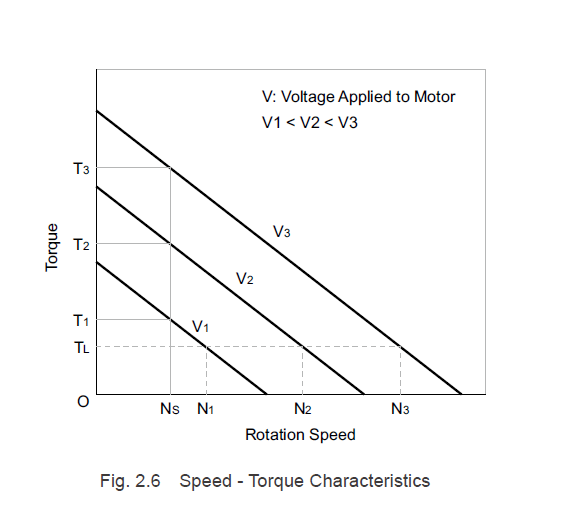
In addition, as shown in Formula (2.3), the generated torque is proportional to the current. For this reason, as the applied voltage increases from V1→V2→V3, the motor current increases and the speed - torque characteristics change. If the applied voltage is changed from V1 to V2 and then to V3 at a constant load torque of TL, the rotation speed will change from N1 to N2 and then to N3. If the applied voltage is V1 and the load torque increases from T1 to T2 or T3, the motor will stop, but if the applied voltage is changed from V1 to V2 or V3, the motor generated torque changes to T2 or T3, and for this reason the motor can operate at the constant rotation speed of Ns.
2.1.4 Brushed DC Motor Features
The features of DC motors with brushes are indicated below.
Advantages
- There are 2 lead wires, and applying a DC voltage is enough to allow rotation.
- Inverting the polarity of the power supply inverts the rotation direction.
- Because permanent magnets are used, DC motors are compact, lightweight, and efficient.
- The starting torque is large and features excellent controllability.
- The torque is proportional to the voltage (current).
- Can be operated with dry cells and batteries.
- Low cost
Disadvantages
- Brush abrasion makes for a short life span.
- Mechanical acoustic noise is generated.
- Electrical noise is generated.
Since DC motors can be operated simply by connecting a DC power supply, they are used for a number of applications. However, because the brushes and commutator sliding against one another causes brush abrasion, cleaning the abrasion powder, replacing the brushes, and other types of periodic maintenance are required. As the number of motors used increases, maintenance becomes increasingly difficult, which increased the demand for a maintenance-free motor with a long life span.
In the next part of this Technical Manual - Brushless Motor Series, we will explain brushless motor structure and principles and compare to brushed motors. Please subscribe to this blog to be notified of future posts!
Interested in learning more?

|
Previous Post
|
Next Post
|


Learn more about Oriental Motor's 
Subscribe (top right corner) to receive monthly updates!