In part 4, we will explain the main components of brushless motors: feedback, magnetic field, and permanent magnets.
| Main Components of Brushless Motors |
2.3.1 Components for Detecting Magnetic Pole
Hall Element
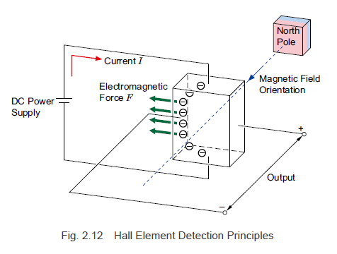
A hall element is a magnetic detection element that utilizes the hall effect to detect the magnetic fields of the rotor magnets and output signals.
The state of a hall element that is affected by the magnetic field from a north pole is shown in Fig. 2.12.
If a current flows from the upper part to the lower part of the element and is affected by a magnetic field from the north pole in the direction indicated by the arrow, the distribution of the electric charges inside the element is unbalanced by the electromagnetic force. As a result, an electromotive force that crosses both the current and the magnetic field at right angles is generated.
The hall element output signal is a weak analog voltage of several 100 mV. If north and south poles continuously alternate as with a motor, then, as shown in Fig. 2.14, there will be a constant output in the areas where the magnetic field is stabilized, and it will change gently in the areas where the magnetic poles switch.
Since the signals are weak, they are easily influenced by noise where the signal lines are long and in environments where there is a lot of electronic noise. A hall effect IC addresses the noise by integrating a circuit that shapes and amplifies the hall element output signals before outputting them.
| TIP: Discovery of the hall effect |
|
The hall effect was discovered in 1879 by American physicist Edwin Herbert Hall. Applying a magnetic field perpendicularly to an object with electricity flowing through it generates an electromotive force perpendicular to both the current and the magnetic field. Hall elements are semiconductors that utilize this principle. The electromotive force continuously changes depending on the strength of the magnetic field. |
Hall Effect IC
A hall effect IC is a magnetic sensor that integrates the hall element and the amplifying and shaping circuit into a single package (IC). Fig. 2.13 shows the internal structure of a hall effect IC, and Fig. 2.14 shows the relationship between the hall effect IC output signals and the hall element output signals in relation to the magnetic fields of the rotor magnets.
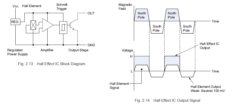
An amplifier is used to amplify the weak output signal resulting from a hall element detecting a magnetic field, and it is shaped using a Schmitt trigger and output. If the magnetic field strength of the rotor magnets exceed the hall effect IC threshold, a signal is output, and if it is lower than the threshold, the signal stops. A hall effect IC is resistant to noise compared to the hall element output voltage, and it is simple to use.
Encoder
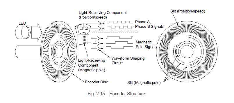
Hall effect ICs detect the magnetic poles of the rotor magnets and perform output, but the encoder converts the light that passes through the encoder disk slit into an electric signal via a light-receiving component, then amplifies and shapes it before outputting the signal.
As shown in Fig 2.15, an encoder is equipped with small slits used for position and speed detection (phase A, phase B), as well as slits for detecting the magnetic pole position. The light-receiving components for detecting the position and speed are arranged such that the signal phase difference as an electrical angle is 90° in relation to the encoder disk slits. Thus, it can accurately detect not only the motor rotation speed but also the rotation amount and rotation direction.
In addition, the 3 slits for detecting magnetic pole positions and the light-receiving components are arranged such that the signal phase difference as an electrical angle is 120°, and the encoder and rotor are separate parts, so the timing of the switching for the rotor magnetic pole positions and the magnetic pole detection signal do not match. To make this timing match, it is necessary to adjust the position of the slits for detecting the magnetic pole position when installing the encoder.
Oriental Motor has products equipped with encoders with magnetic pole detection signals. Since the rotation speed and rotation amount can be accurately detected via the phase A and phase B signals, stable speed control at low speeds, and position control are possible.
2.3.2 Components That Generate Magnetic Fields
With induction motors, torque is generated via the current induced in the rotor and the rotating magnetic field in the stator, but with synchronous motors such as brushless motors, torque is generated via magnetic fields from permanent magnets and the rotating magnetic field in the stator. Here, we will explain the permanent magnets in the main components that are crucial for supporting the compact size, high output power, and high efficiency brushless motors are known for.
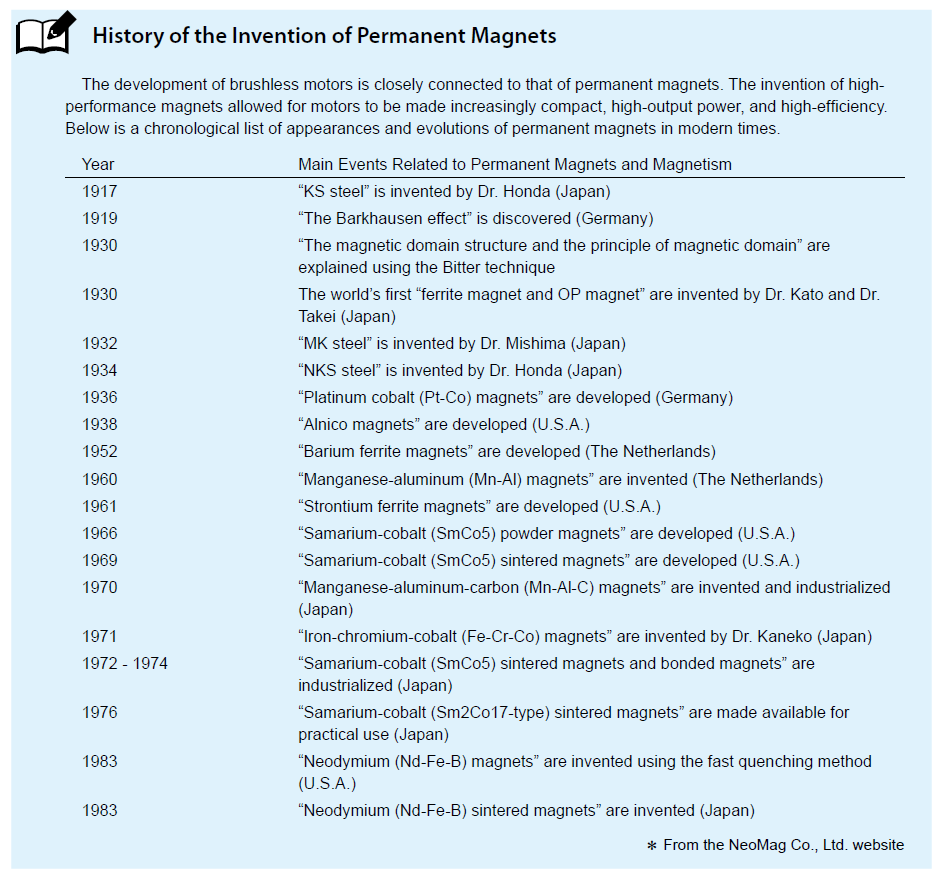
Ferrite Sintered Magnets
The ferrite sintered magnet was invented by a Japanese person in 1930. Since ferric oxide is the principal component, it is cost-effective. In addition, because no surface treatment is required, it has good cost performance, and it is still the most commonly produced and used magnet worldwide.
Maximum energy product (BH) max 8.0 to 43.8 kJ/m³ [1.0 to 5.5 MGOe]
Rare Earth Sintered Magnets
There are samarium-cobalt (SmCo) varieties and neodymium (NdFeB) varieties, with neodymium magnets having the highest performance, making them essential for compact, energy-saving motors. However, because few countries produce the rare-earth elements used to make them, few are produced, and they are expensive.
Maximum energy product (BH) max 199 to 414 kJ/m³ [25 to 52 MGOe]
Bonded Magnets
These magnets are molded and manufactured by mixing fine magnetic powder from ferrite and rare-earth magnets with resin and other binders. Since they can freely assume many shapes, they have excellent workability in assembly and jointing work, but because they contain non-magnetic components, their magnetic properties are half or less than those of sintered magnets.
Maximum energy product (BH) max
Neodymium type: 63 to 159 kJ/m³ [89 to 20 MGOe]
Ferritic 5.6 to 17.5 kJ/m³ [0.7 to 2.2 MGOe]

|
Previous Post
|
Next Post
|


Learn more about Oriental Motor's 
Subscribe (top right corner) to receive monthly updates!