This is a continuation of the blog post, "Technologies Used with Brushless Motors". In this section, we explain the efficiency aspect of brushless motors and compare them to AC motors.
| 5.5 High Efficiency, Energy Saving |
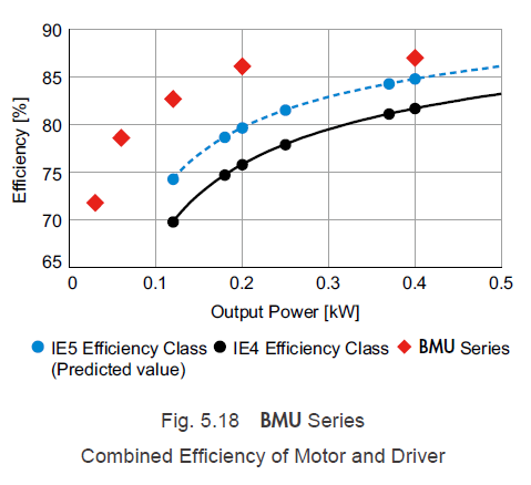
According to the World Energy Outlook 2016 published by the IEA (International Energy Agency), over half of the world's total power consumption is motor-related. Reducing energy consumption is a global issue, and with regards to making motors more highly efficient, International Standard IEC 60034-30-1 defined efficiency classes aimed at induction motors from 120 W to 1,000 kW. Currently, classes of up to IE4 have been established, but an IE5 efficiency class will be introduced, which is supposed to reduce the loss from an IE4 motor by 20%. Please refer to Fig. 5.18.
Brushless motors with built-in permanent magnets do not fall under IEC 60034-30-1, but they are more efficient than three-phase AC induction motors, and the efficiency of a motor combined with a drive circuit exceeds that of the IE5 efficiency class (the expected values). Here, we will explain the loss reduction technology of brushless motors, primarily using Oriental Motor's BMU Series products as examples.
5.5.1 Motor Loss
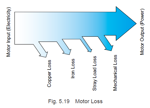
Loss categories are shown in Fig. 5.19. Motor loss is divided into copper loss, iron loss, stray load loss, and mechanical loss. In general, a large amount of motor loss is comprised of copper loss and iron loss. In addition, the smaller the motors, the larger the ratio of copper loss becomes, so it is important to take effective countermeasures to reduce loss based on the size of the motor.
Next, we will explain the main types of loss and technology for reducing loss.
5.5.2 Copper Loss
Copper loss refers to joule loss resulting from currents flowing through copper wires, and it can be calculated using the below formula.
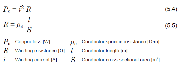
As shown in Formula (5.4), the copper loss decreases as the current value and winding resistance value becomes lower. In addition, Formula (5.5) shows that the winding resistance value becomes lower, the larger the conductor cross-sectional area becomes, allowing the copper loss to be reduced. For this reason, it is crucial to wind a thick copper wire with a high space factor. The ratio of the slot cross-sectional area (the area of section of the stator with the copper wire windings) occupied by the copper wire is referred to as the space factor, and the higher this value is, the less unused space there is among the copper wire windings.
a. Reduction in the Current Value
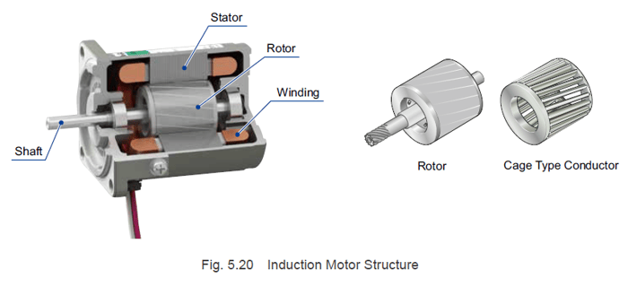
Induction motors generate torque when an induced current flows through the cage type conductor inside the rotor due to the rotating magnetic field created by the stator. For this reason, winding currents contain currents used to generate torque and currents used to create induced currents. In addition, copper loss occurs in the stator windings and cage type conductor due to winding currents and induced currents.
Because brushless motors use permanent magnets in their rotors, induced currents are not necessary. Since only currents that generate torque are required, they can reduce winding current, unlike induction motors. Since there is no copper loss in the rotor and the copper loss in the stator windings can be reduced, there is less copper loss than with induction motors.
b. Reduction in the Winding Resistance Value
Brushless motors developed in recent years, including the BMU Series, use neodymium sintered magnets with six times the energy product of conventional neodymium bonded magnets. Because the magnetic flux density from the rotor magnets has increased, the number of turns in the coil can be reduced compared to conventional products with the same output power.
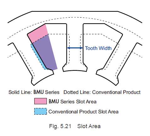
However, since the magnetic flux density has increased, it is necessary to expand the tooth width, as shown in Fig. 5.21. To address this, a frameless structure that does not use a motor case is utilized, and the external diameter of the stator iron core is increased, which raised the slot area. In addition, technology for increasing the wire alignment was developed. These measures have made it possible to use a thicker conductor, allowing the winding resistance and copper loss to be reduced.
Furthermore, the increased magnetic flux density not only allows for the coil to have fewer turns, but it also allows the length of the stator core to be shortened.
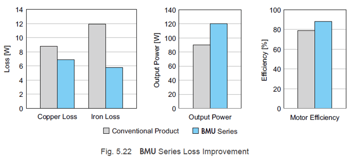
The BMU Series, through high performance magnets and increased space factor through improved stator shape and winding technique, has half the stator core length and 11% less copper loss compared to conventional products.
5.5.3 Iron Loss
Iron Loss is divided into eddy current loss and hysteresis loss. Eddy current loss occurs within the core due to the time variation of the magnetic flux density and flow through the stator core and rotor core. Hysteresis loss occurs in magnetizing energy resulting from alternating magnetization. They are represented by the following formulas.
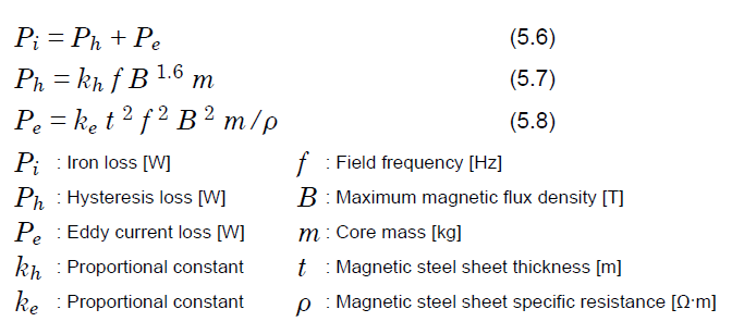
As shown by Formula (5.7) and (5.8), the elements related to motor iron loss can be divided into:
- the proportional constant and the specific resistance, which are determined by the magnetic steel sheet material
- the thickness of the magnetic steel sheet
- the field frequency, the maximum magnetic flux density, and the core mass, which are determined by motor design
To reduce the iron loss in the motor, a magnetic steel sheet that is thin, has low iron loss, has a high saturation magnetic flux density, and has good frequency dependence is ideal, but each of these characteristics has a trade-off. In addition, because there is a need to consider processability and cost, which characteristics are used depends on the required motor characteristics. Regarding design-related elements, it is necessary to optimize the magnets used and the balance between copper loss and iron loss.
| TIP: Hysteresis loss vs eddy current loss |
| For more information on hysteresis loss and eddy current loss, please refer to Design World's article, "Hysteresis loss and eddy current loss: What’s the difference?" on Motion Control Tips. |
The BMU Series and BLE2 Series next generation brushless motors utilize high performance magnets to make the stator length half that of conventional motors, and combine this with high performance magnetic steel sheets to reduce iron loss by 50%. Utilization of technologies such as these allows the BMU Series to have a total length that is 12% shorter than that of conventional products, with 33% higher output power and 7% higher efficiency.
5.5.4 Stray Load Loss
The loss that remains after subtracting copper loss, iron loss, and mechanical loss from the total motor loss is the stray load loss. Conventionally, this was treated as a loss whose causes were unclear. However, due to improvements in analysis technology in recent years, stray load loss gained visibility as local loss due to leakage flux and so on.
5.5.5 Mechanical Loss
Mechanical loss in motors refers to friction loss from the bearing, oil seal, and other mechanical contact areas. An example is the windage loss due to the types of cooling fans installed in most induction motors. With brushless motors, there is little loss, and internal cooling fans are not necessary, so the mechanical loss can be suppressed.
| 5.6 Small and Lightweight Motors |
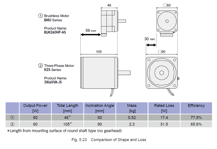
Brushless motors are smaller and lighter than three-phase AC motors while still offering the same rated output power. A motor's rated output power is the output power at which the temperature rise in the parts used (mainly the winding) satisfies the permissible temperature range when the motor is operated continuously under certain conditions determined by the specification, such as ambient temperature and supply voltage.
Due to the high efficiency, energy-saving technology explained in "5.5 High Efficiency, Energy Saving", brushless motors have little motor loss. The temperature rise in the motor balances loss with the heat release, so the less loss there is, the smaller the motor can be.
A comparison of the shapes and loss amount of a brushless motor and a three-phase AC motor with the same output power is shown in Fig. 5.23.
Since the motor is small and lightweight, this leads to the machine being smaller and lightweight as well. In particular, with battery-driven vehicles, small size and lightness are emphasized because they are directly related to how long the vehicle can be driven.
Thanks for reaching the end of this Technical Manual Series. If you have any questions or would like to learn more, please consult with our team via live chat, phone, or e-mail.
|
Previous Post
|
Next Post N/A |

Learn more about Oriental Motor's 
Subscribe (top right corner) to receive monthly updates!