The level of troubleshooting you can perform depends on your knowledge of the system. This technical article provides the basics of troubleshooting for stepper motor systems from my experience as a technical support engineer.
When a stepper motor stops working, it could be caused by either something as simple as a loose wire or something more complex as a missing line of code in its program. The latter cause is much more difficult to find. In most cases, a process of elimination is necessary to guide yourself to the right solution.
The first thing you should understand is the entire system that commands the stepper motor to move. The diagram below shows a host controller, a pulse generator, a stepper motor driver, and a stepper motor.
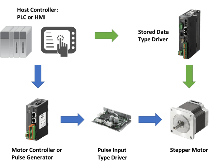
You'll have to know what type of driver you have. Pulse input type drivers require a pulse train command from an external source; stored data type drivers do not. The blue arrows show the system configuration with a pulse input type driver, while the green arrows show the system configuration with a stored data type driver. Since a stored data type driver contains a built-in controller that stores motion data and generates pulses, the motor controller (pulse generator) can be eliminated.
Functions of each device in the system:
Host Controller - also known as a programmable logic controller (PLC) or human machine interface (HMI). This is the brain of the entire operation that processes information and outputs commands to the controller with its I/O either through physical connections or network command.
Controller - traditionally called a pulse generator. This device outputs digital square wave pulses to the driver and controls the movement of the stepper motor shaft. Each pulse is an incremental "step" on the motor shaft. Pulse speed in Hz controls the speed of the motor shaft.
Driver - also known as the amplifier of the stepper motor. This device energizes the stepper motor with current and determines the phase excitation sequence. Some drivers are more intelligent than others as they also include a controller function that can store motion data.
Motor - this is the stepper motor where the load is connected to. It just does whatever it's told to do.
The following are examples of the most common problems that may occur when using stepper motors.
- The motor does not move, or it does not have holding torque.
- The motor moves, but the operation is abnormal.
- The motor moves, but there is a position error.
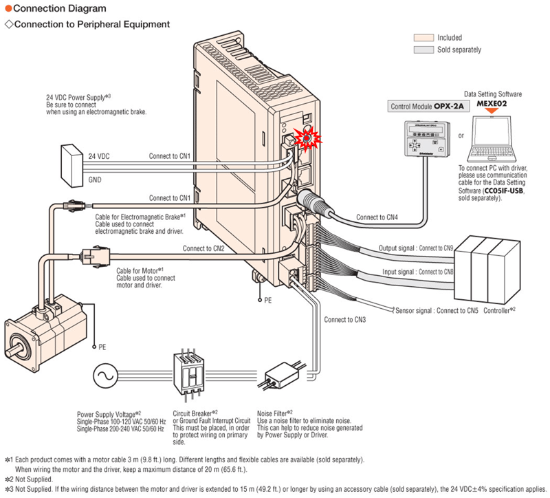
When troubleshooting a stepper motor system, all components that can affect operation should be checked. The diagram below shows all of the components when connected to the driver. Since this is a stored data type driver, no motor controller (pulse generator) is necessary, and it can be connected directly to a host controller*², such as a PLC or HMI.
The secret to troubleshooting is to start from the most common causes and narrow down possible causes from there. We will show you how, but first, we need to check the most obvious causes.
| Basic Checks | "My motor is not moving." |
Is the power on?
All devices should have an LED to indicate ON status except for the motor. Check if the stepper motor has holding torque. If it does, then the motor is energized.
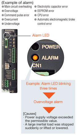
Is there an alarm?
If the alarm LED blinks, please count the number of blinks in a row, then refer to the operating manual for more information on the alarm codes.
Is the motor connected properly?
Make sure all wires from the stepper motor are connected to the right terminals on the driver or connector pins. Even if one motor lead wire is disconnected, it can cause a shortage of torque, excessive noise, vibration, and/or position error.
Is the motor bad?
There are two things to check if a motor is bad. The ball bearing and the motor windings.
| TIP |
It's easy to check for bearing damage. First, disconnect the motor from the load and driver, then try to rotate the shaft by hand. However, make sure that the lead wires are not touching each other as it will "lock" the phases and prevent motor rotation. Simple experiment: twist all the lead wires together, then try to rotate the shaft by hand. |
Since the rotor contains a rare earth magnet, you would feel the cogging torque as you twist the shaft, and it breaks from one magnetic field to the next. This is normal. If the shaft rotates without any issues, or if you don't feel excessive friction, then the ball bearing is good. If the bearing was damaged, it would be very difficult to rotate the shaft. In this case, replace the motor.
For geared stepper motors, there's also a ball bearing in the gearbox. However, it takes a lot more torque to rotate a gearbox shaft by hand. Since the load is mounted to the gearbox, the gearbox bearing would break before the motor bearing.
| Problem 1 | The motor does not move, or it does not have holding torque. |
For a stepper motor to rotate, two things have to be true:
- The motor has excitation
- The driver receives pulses
When a stepper motor is excited, it means that it's energized with current output from a driver. Current is proportional to torque, so without current, the motor would have no power to generate holding torque or rotate. You can confirm this by feeling for the existence or absence of holding torque on the motor shaft. With holding torque, it should be very difficult for you to rotate the motor shaft by hand.
In order for a stepper motor to have excitation,
- The power supply (for the driver) is switched on.
- There is no motor winding damage.
- The driver outputs the correct amount of current to the motor.
👉 To verify if the driver has proper power, please check the LED of the driver. If everything is working properly, you should have a green LED and no blinking ALARM LEDs. If the ALARM LED is blinking, please count the number of blinks, then refer to the manual for more information about alarm codes.
If you're sure you are providing the right power supply to the driver, but the LED isn't turning ON, then perhaps the fuse has been damaged. In this case, please replace the driver.
👉 To verify if the motor winding is good or not, first remove the load from the motor and disconnect it from the driver.
Measure either full or half coils of the windings according to your wiring method (and type of driver). Please see below for more information on how to measure with an oscilloscope. Depending on the wiring configuration, you either measure the full coil or half coil of the windings by performing a resistance test with the motor lead wires.
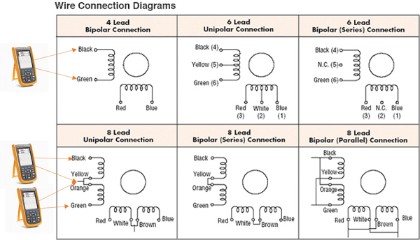
If the right pair of wires are measured, all measured values should be within +/-10% of each other. If so, then the motor windings are good. If you read either 0 Ω or more than several KΩ, then a wiring error or an open connection may have occurred. If the variation in resistance is 1.3~1.5 times more, then it may be a miswiring.
The resistance values are not always published or labeled. Please contact our helpful technical support team if you need more accurate data.
| TIP |
When you perform measurements with the motor lead wires, make sure that the lead wires are not touching each other as it give inaccurate readings. |
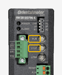
👉 To verify if the right amount of motor current is set up correctly, you'll have to check the motor current setting either with analog potentiometers on the driver itself or within the software parameters. Make sure the RUN current is set to "full".
 |
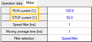 |
| TIP | In cases where full torque isn't needed, the RUN current can be lowered to decrease operating temperature, which in turn increases long-term bearing and motor life. |
👉 Is there an input disabling the motor?
Certain drivers offer an input to disable/de-energize the stepper motor so troubleshooting or other work can be done. The input can be named "FREE" (turn on to de-energize the motor) or "C-ON" (turn on to energize the motor). Make sure this input is in the right state.
👉 Is the TIM. signal blinking while pulses are being fed to the driver?
The TIM. output LED blinks when the driver is receiving a steady stream of pulses. This LED blinks every electrical cycle of the motor. This means the LED blinks every 4th pulse received (for 2-phase stepper motors), and the LED blinks every 10th pulse received (for 5-phase stepper motors).
| Problem 2 | The motor moves, but the operation is abnormal. |
If the motor moves, but the operation involves the motor not following the input command from the host controller, then additional checks are needed for the wiring between the host controller and the driver.
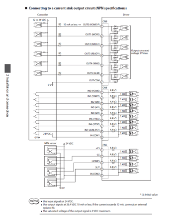
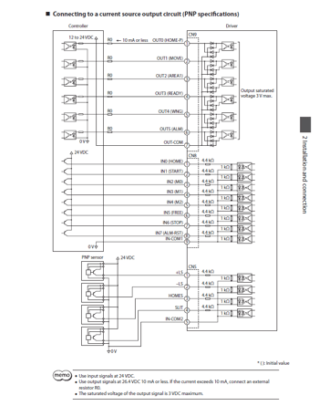
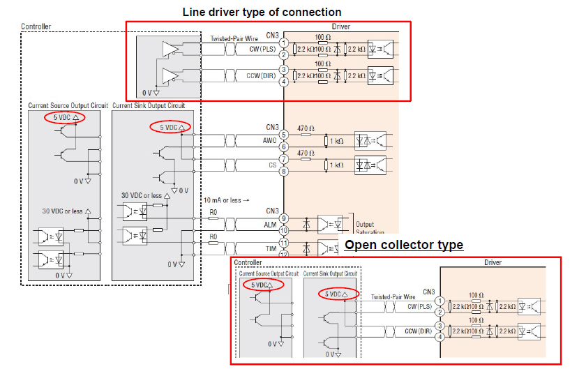
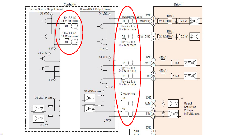
👉 To verify the wiring, compare the actual wiring with the wiring diagram. Make sure to refer to the correct wiring diagram. We show wiring diagrams to connect to either current sink output circuits (NPN) or current source output circuits (PNP).
| Connecting to a current sink output circuit (NPN) | Connecting to a current source output circuit (PNP) |
 |
 |
For additional assistance, our technical support engineers are well-versed at explaining wiring diagrams.
Now, if you have confirmed holding torque and the driver is receiving pulses, but the stepper motor doesn't move or only moves in one direction, check the 1P/2P mode switch (for pulse input type drivers only).
👉 To verify the pulse mode, look at the dip switch settings on the front of the driver.
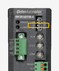
"1P" means "1 pulse mode", and "2P" means "2 pulse mode". This determines how the driver understands the pulse signals that it's receiving. In 1 pulse mode, the controller provides a pulse signal and a direction signal. The pulse signal is a continuous stream of digital pulses, while the direction signal is either ON or OFF. In 2 pulse mode, the controller provides 2 sets of pulse signals (one for each direction).
Here's an excerpt from the manual that shows the pin-outs of the CN4 terminals.
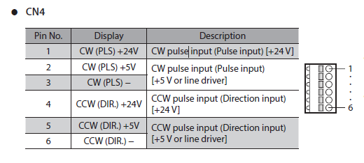
In 1-pulse mode, pins 1~3 are designated for PLS (pulse input), and pins 4~6 are designated for DIR (direction input). For example, if your pulse/direction signal is 24VDC, then connect to pins 1, 3, 4, and 6.
Pins 3 "CW (PLS) -" and 6 "CCW (DIR.) -" are the common GND for 24VDC or 5VDC signals.
In 2-pulse mode, pins 1~3 are designated for CW (clockwise pulse input) and CCW (counterclockwise pulse input). For example, if your CW/CCW pulse signals are 5VDC, then connect to pins 2, 3, 5, and 6.
Here's a timing chart that shows the input signals in 1-pulse or 2-pulse mode.
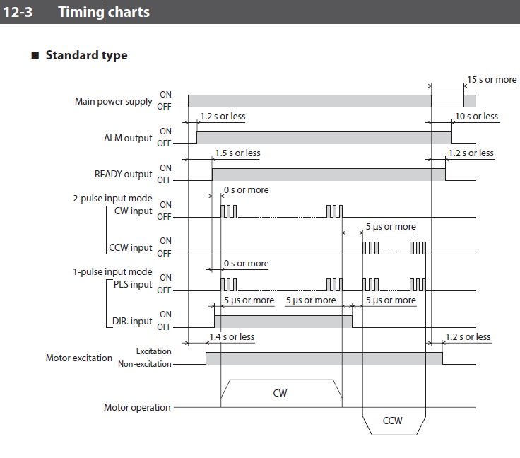
With a deeper understanding of how the inputs are supposed to work, you can perform isolated tests on each input to determine if it's working properly. Don't forget to check if the TIM LED blinks.
Now, if the motor has holding torque and is receiving pulses, but it's making a loud noise while not moving or tending to skip steps, then we have an overload condition. An overload condition can be caused by insufficient torque from the motor or an overly aggressive motion profile (which creates more acceleration torque).
👉 To verify an overload condition (easy check), remove the load from the motor, then run the same motion profile again. If it works, then you know you have a load issue.
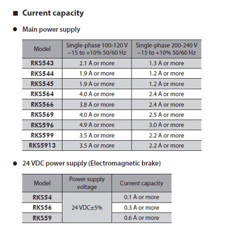
👉 To verify if the power supply is causing insufficient torque, check the power supply's specifications and compare the current rating to the driver's power supply specifications. If the power supply meets the voltage specifications but not the current specifications, then it would explain why the motor outputs less torque.
Also, remember to use a sufficient power supply in order to release the electromagnetic brake properly.
👉 To verify if there's something wrong with the motion profile, a good trick is to lower all of your speed parameters to a crawl (starting speed, operating speed, acceleration, deceleration), then run the motion profile in test mode within the MEXE02 software to see if it works. If it works, then it means your motion profile was too aggressive.
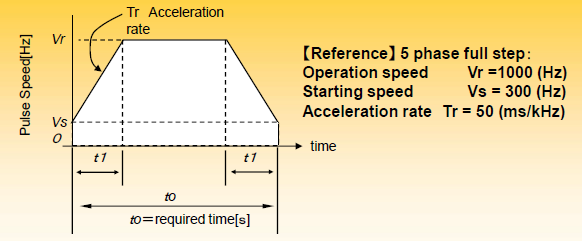
The parameters of a motion profile that affects torque the most would be Vs (starting velocity), t0 (total move time), and t1 (acceleration/deceleration).
| TIP | It's always a good rule of thumb to size a stepper motor for the most aggressive motion profile that is necessary for the application. If you know the motor can do the most aggressive motion profile, then all other motion profiles would work. |
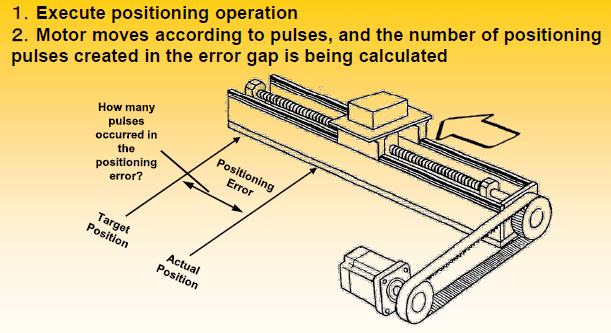
| Problem 3 | The motor moves, but there is position error. |
There's actually error for each step that a stepper motor takes. However, they're always under the specification of +/-0.05° and they're not cumulative.
👉 To properly troubleshoot, it's important to understand when the error occurs and exactly how much error there is. Therefore, you'll need to look for patterns and calculate the position error by comparing the actual position vs the target position. If a stepper motor is coupled to a ballscrew for linear positioning, then you must convert the linear error from mm or inches to steps, pulses, or degrees.
| TIP | A stepper motor typically misses steps in multiples of 7.2°. If the stepper motor is not missing steps in multiples of 7.2°, then it must be something else creating the error, such as an incorrect number of pulses. To verify the number of pulses received, you can use an oscilloscope. |
Common mistakes to watch out for:
➡️ Make sure to understand wiring diagrams and follow them properly. Pay attention to the type of circuits and logic, such as line driver vs open collector type.
➡️ For certain inputs or outputs, external resistors are necessary to limit the current. For example, the "R1" resistor limits the current on 24VDC signals. For 5VDC signals, external resistors are not necessary.
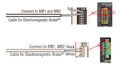
➡️ Make sure to connect a power supply for the MB1/MB2 inputs in order to properly release the electromagnetic brake (only applies to electromagnetic brake type stepper motors).
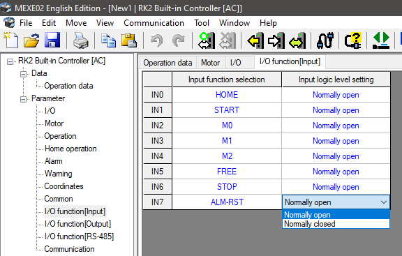
➡️ Make sure to set up your input function selection and input logic level setting within the MEXE02 software. Dip switches and/or software settings can change how inputs work on a driver.
Troubleshooting can be tricky if you aren't sure what you're doing. We would suggest creating a standardized procedure so you don't miss any steps and end up spending more time than you should.
This article is designed to provide basic troubleshooting tips for stepper motors. If you require additional assistance, please contact our helpful technical support team.