Building a robot is not easy. Programming a robot can be even more challenging without user-friendly software. In this article, I'll explain a few of the MRC Studio's most useful features and demonstrate how the Robot Vision Calibration function can help reduce costs for your vision-enabled robots.
What's covered?
- What is the MRC Studio Software?
- What Makes the MRC Studio Software Easy to Use?
- What Types of Robots Can Be Controlled By The MRC Studio Software?
- TIP: Use the Vision Calibration Function of The MRC Studio Software to Simplify System Configuration and Reduce Costs
- Application Demonstration
- Play-By-Play
- Summary
What is the MRC Studio Software?
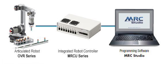
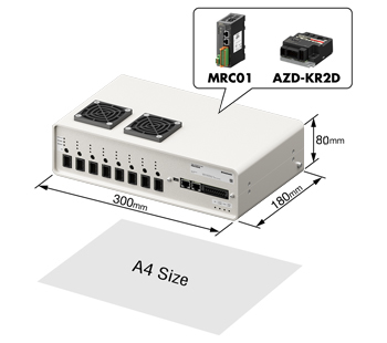
The MRC Studio software is the dedicated robot programming software for the MRC01 Robot Controller and MRCU Series Integrated Robot Controller. The MRC01 robot controller and the MRCU Series integrated robot controllers are used to control all the axes of the OVR Series Small Industrial Robots, or up to 8 axes of motion on a custom robot built with motors, actuators, and drivers from the αSTEP AZ Series Hybrid Step-Servo Product Family.
The MRC Studio software makes it easy to program coordinated motion for multi-axis robots. Since no ladder logic experience is necessary to learn how to use this software, even someone with no prior programming experience can learn to program complex palletizing operations in minutes instead of hours.
What Makes the MRC Studio Software Easy to Use?
☑️ Easily drag and drop required commands from a menu
The MRC Studio software supports a range of advanced motion control operations for robots, including point-to-point, linear interpolation, circular interpolation, and arc motion, among others. Easily drag and drop commands from a menu to build your motion sequence program. Operating data can be executed from a host controller via EtherNet/IP commands or digital inputs.
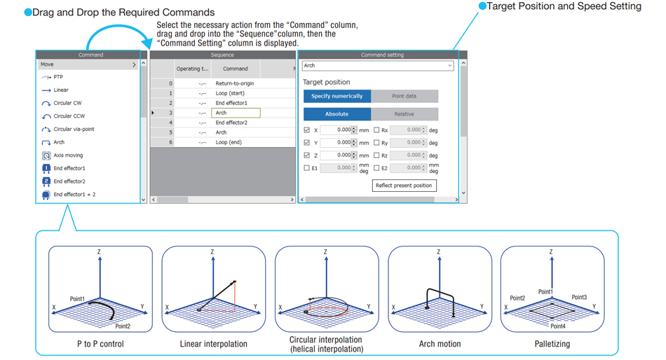
If standalone operation is desired, digital inputs via relays are also possible. An MRC Studio Simulator version of the software is also available for users who want to test it out before purchasing a robot.
| ☑️ Use Live Motion Simulator to test motion | ☑️ Use MRC Reality to simulate the robot |
|
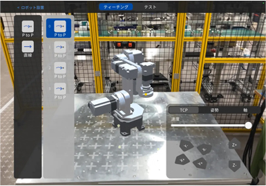
Use the Graphic Monitor in the MRC Studio Simulator to simulate the operation program live in a 3D environment and verify the robot motion before implementation. |
Use the MRC Reality app with a smartphone, tablet, or head-mounted display to simulate the robot operating in your specific environment. |
 |
 |
What Types of Robots Can Be Controlled By The MRC Studio Software?
| The MRC Studio programming software can control up to 8 axes of robot motion. This means it can control 3~6 axis articulated robots, SCARA robots, and cartesian robots from the OVR Series (+ up to 2 end-effectors) or custom-built robots using motors, actuators, and drivers from the AlphaSTEP AZ Series Hybrid Step-Servo product family. | 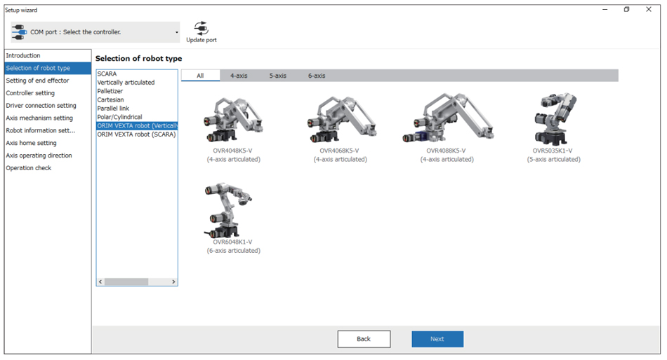 |
| TIP | Use the Vision Calibration Function of The MRC Studio Software to Simplify System Configuration and Reduce Costs |
The MRC Studio software and the MRC01 Robot Controller offer a unique built-in semi-automatic function that can simplify and reduce costs for your vision-enabled robots. By using the Robot Vision Calibration function, position and angle information of the load captured by the camera, and the data can be applied to the coordinate system of the robot. This means that any 2D camera with X, Y, and angle data output and EtherNet/IP communication can be used to perform highly accurate adjustments of the loads picked up and placed by the robot.
| The MRC Studio software supports 2 camera calibration methods: the "fixed camera method" and the "hand-eye method". In the fixed camera method, the camera is installed in a permanent location away from the robot. In the hand-eye method, the camera is installed on the robot and moves with the robot. |  |
How Does the Robot Vision Calibration Function Work?
|
Here's what you'll need to make it work:
|
 |
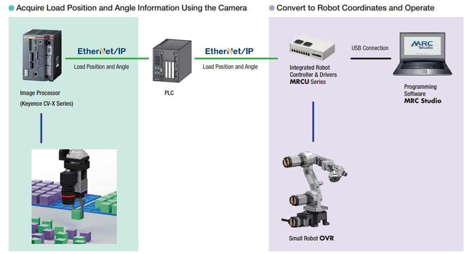
The camera located on the end-effector at the end of the robot arm captures an image of the load. The image processor processes the image and sends the image coordinates to the PLC, which in turn relays the coordinates to the MRCU Series integrated Robot controller via Ethernet/IP command. Since MRCU handles the calibration and conversion of image coordinates into robot coordinates, MRCU will convert and command all the axes of the robot to move the TCP (Tool Center Point) to those robot coordinates.
Since the MRC Studio software offers a built-in vision calibration function, an image processing device without calibration capabilities can be used, which reduces the overall cost.
|
By using EtherNet/IP commands with the MRC robot controller and the Robot Vision Calibration function of the MRC Studio software, it can automatically pick up loads that have been placed in random positions, handle different load shapes, and place loads at exactly the same angle and orientation every time. Even without a host controller, robot vision calibration can still be performed as long as the camera and robot are installed. |
 |
For more information about the Robot Vision Calibration function, please refer to "Chapter 4-5: Operation where MRC01 controller and camera are used in combination" on page 132 of the MRC01 user manual.
Application Demonstration
We built a robot and conveyor automation demo to showcase a revolving robotic pick-and-place process, a common method used to perform warehouse automation tasks, such as picking, packing, shipping, receiving, unpacking, and stocking. The demo also includes a palletizing operation that uses the Vision Calibration function to place the model cars in the same orientation. This demo was first introduced at Automate 2025 in Detroit.
The 4-axis OVR Series articulated robot on the left uses a Schmalz vacuum gripper as its end-effector to place or remove the top covers of the clear plastic boxes, and the 5-axis OVR Series articulated robot on the right uses an EH Series 2-finger gripper as its end-effector to grip the rectangular loads (model cars) and place them neatly in the clear plastic boxes. The 2 conveyors moving the loads back and forth are driven by BLH Series brushless DC gearmotors. A Cognex In-Sight 2802 Series vision system is installed above the robot on the right side. For the host controller, we're using a Rockwell Automation Allen Bradley Compact Logix 1769 Series PLC.

Play-By-Play
1. When the loads are inside the picking area, the MRC01 Robot Controller sends a Remote Output command "PRG-ROUT0" to the Cognex In-Sight 2802 series vision system to trigger the image capture.
The Remote Output command (from Remote-I/O) is sent from the MRC01 Robot Controller to the Cognex camera through Ethernet IP communication using a PLC from the Allen Bradley Compact Logix 1769 series.


2. When the command is transferred from Allen Bradley Compact Logix PLC, the Cognex In-Sight 2802 vision system captures the target images.

3. Cognex In-Sight 2802 Vision Suite software compares the captured image with the pre-registered image, and locates the most recognized image's position in terms of vision coordinates.

4. The MRC robot controller sends another Remote Output command "PRG-ROUT1" to acquire the captured coordinate data from the Cognex In-Sight 2802 series vision system to the MRC01.

| 5. Upon receiving the vision coordinates (X, Y, and angle data), the MRC01 robot controller and MRC Studio software convert the vision coordinates to the equivalent robot coordinates in reference to its TCP (Tool Center Point) and move the arm to the position. |  |
On the left, we created a video to show you how to program the robot and camera using the vision calibration software function (before). Follow along for step-by-step programming instructions. On the right, we created a video to show you what it should look like once it's working properly.
| BEFORE (How to Program) | AFTER (What It Looks Like) |
Summary
The article introduces the MRC Studio software, a user-friendly robot programming software for the MRC01 Robot Controller that's designed to control OVR Series small industrial robots or custom-built robots using products from the αSTEP AZ Series Hybrid Step-Servo product family. The MRC Studio simplifies multi-axis robot programming with features such as drag-and-drop commands, live motion simulation, and AR-based environment modeling with the MRC Reality app.
A standout feature is its Robot Vision Calibration function, which enables precise load handling using 2D cameras and EtherNet/IP communication. This function supports both fixed camera and hand-eye camera setups, allowing robots to automatically align and orient loads in a pallet—even when randomly placed—without requiring complex programming or expensive hardware.
By integrating vision data and converting vision coordinates into robot coordinates, the system reduces setup time, improves accuracy, and lowers overall costs. An application example using Cognex cameras and Rockwell PLCs demonstrates how the calibration process works in real-world automation.

Interested in more details and videos of the pick and place demo?

 |
 |
Download the MRC Studio, MRC Studio Simulator, or MRC Reality
Related articles: