Oriental Motor provides a wide variety of products to meet semiconductor equipment design goals. This post focuses on motor selection for two specific motion axes of a semiconductor manufacturing process called CMP (Chemical Mechanical Polishing) and explains how to save time by using different products from the same family.
|
Jump to section: |
First, let's understand the assignment. What does a CMP tool do, and what kind of motion do we need?
What is Chemical Mechanical Polishing (CMP)?
|
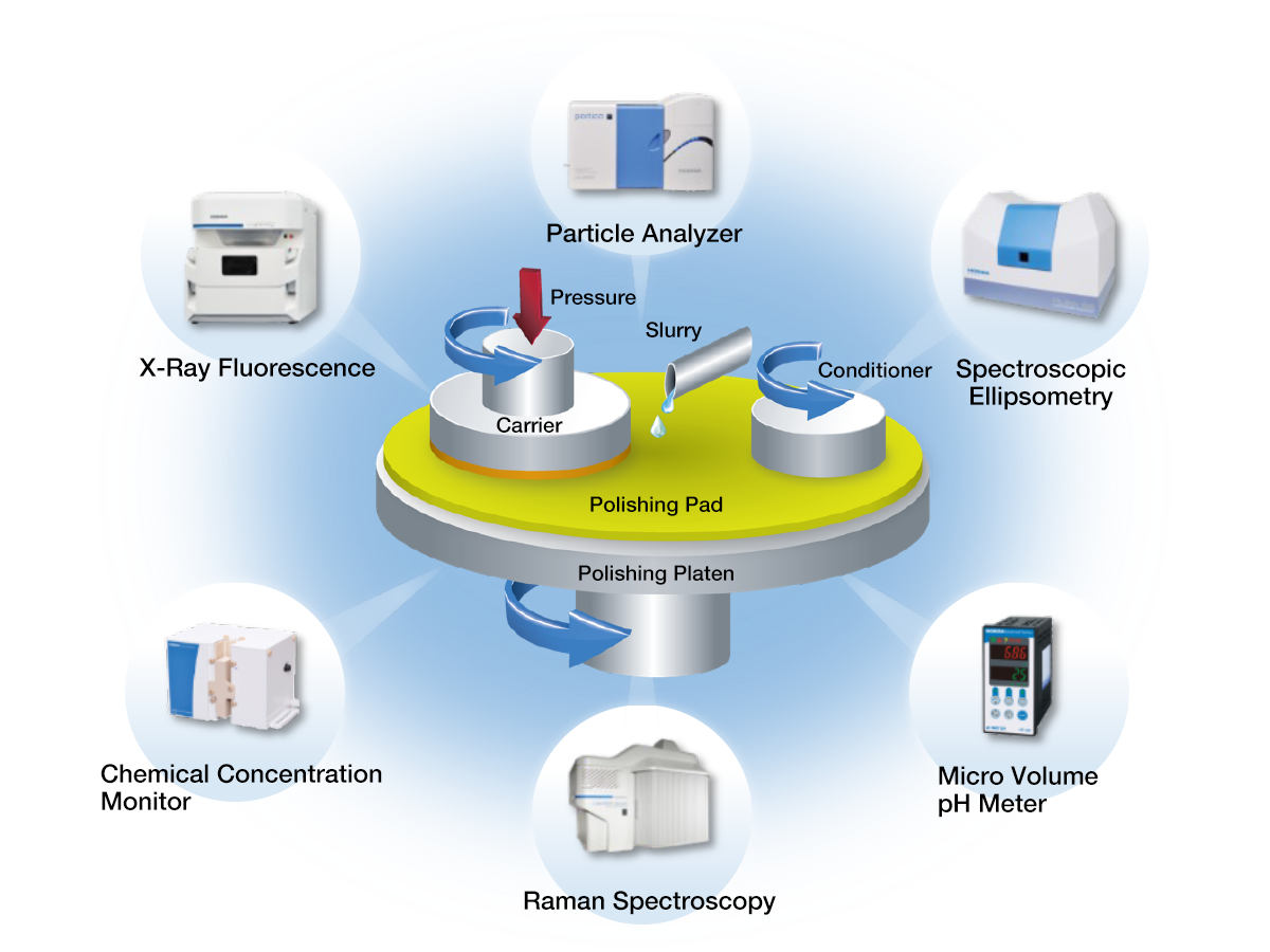
Chemical Mechanical Polishing (CMP) is a process in integrated circuits manufacturing to make the surface of a wafer perfectly flat (planarization). To review, a wafer is a thin slice of semiconductor material and can be made with silicon or germanium. To make a wafer surface flat, it needs to either remove excess material or create a perfectly flat foundation for the next layer. |
Source: Horiba Semiconductor |
The CMP process became more critical in the 1980s and 1990s as more semiconductors used more layers. Uneven surfaces between layers and tiny imperfections can cause issues with current flow, heat dissipation, or component life. CMP combines physical grinding and physical etching to smooth out the surfaces of semiconductors within a tolerance of 0.2 microns (less than one-thousandth of a millimeter).
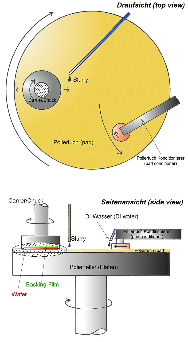
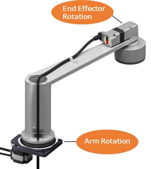
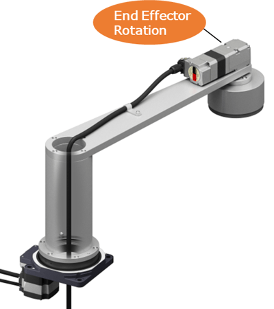
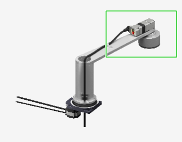
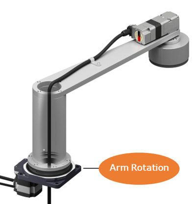
A CMP tool employs multiple swing arms above a rotary table to move the carrier/chuck and pad conditioner into position. Let's see what the swing arm looks like.
| Top/Side View of CMP Tool | Swing Arm with Oriental Motor Products |
|
Source: https://en.wikipedia.org/wiki/Chemical-mechanical_polishing |
|
How does CMP work?
To remove excess material, the CMP process needs to polish one side of the wafer so it's planarized. First, the polishing pad needs to be conditioned by the pad conditioner, which requires a swing arm to move it into position, then move it back and forth across the polishing pad. De-ionized water is also dispensed on the polishing pad to help improve polishing performance and extend life.
After this process is done, another swing arm needs to move the wafer onto the polishing pad before the polishing can begin. The backside of a wafer is mounted to the carrier/chuck on the end of the swing arm. A chemical slurry is dispensed on the polishing pad as the front side is pressed and polished against the polishing pad. At this time, the carrier/chuck moves the front side of the wafer in a forward and back motion against the abrasive polishing pad, which also rotates at the same time.
CMP slurries are typically made from a nano-sized abrasive powder in a chemically reactive solution. Chemical etching softens the material as mechanical abrasion removes the material.
In total, two swing arms are necessary to move the carrier/chuck and the pad conditioner, and a rotary table is necessary to rotate the polishing pad. In addition, linear actuators can move the carrier/chuck or pad conditioner assemblies up and down to provide additional force/pressure.
To guarantee that the right amount of material is dispensed evenly across an entire wafer, a CMP process must be able to measure the film thickness, apply varying amounts of forces during material removal, and stop precisely.
We learned that one of our customers used three hollow rotary actuators and two motors for the two swing arms and polishing table in their CMP process. While a larger rotary actuator rotated the polishing table underneath, each swing arm would use a rotary actuator at the base to rotate the arm, and another motor to spin the polishing pad.
For this post, we will focus on the motor selection for the swing arms.
Motor Selection
It's important to select motors that can provide precise positioning control for the swing arm and variable speed accuracy for the polishing pad. These motors will need to respond quickly to avoid polishing too much of the substrates away.
However, we also learned from one of our main customers from the semiconductor industry that a CMP tool requires motors that are a bit more advanced, such as having the ability to control torque and operate in absolute coordinates.
We broke the motor selection criteria down into two axes: arm rotation and end effector rotation.
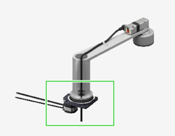
Swing Arm Axis (or Conditioner Axis)
Purpose: the motor needs to position the swing arm in place before the polishing or conditioning can begin.
 |
|
|
Requirements Met: |
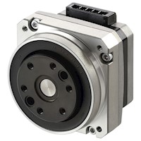
Advantage Large Hollow Bore Diameter |
|
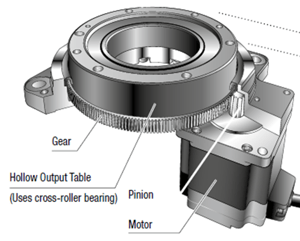 |
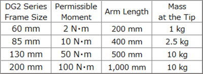
Here's a reference table showing the approximate mass that the swing arm like this can handle at the end of the arm. Our technical support engineers are trained to help you with the motor sizing process.
Polishing Axis (End-Effector)
Purpose: the motor will need to rotate the wafer at a certain speed against the friction from the polishing pad.
|
|
|
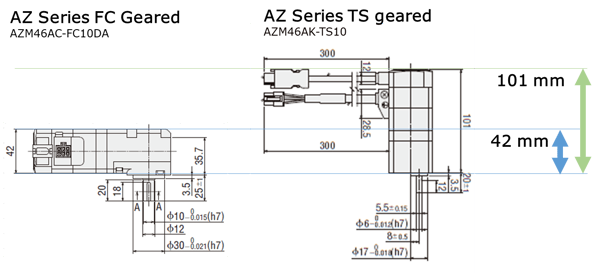
One swing arm would carry the polisher head, and the other swing arm would carry the conditioner. The FC right-angle geared type motor minimizes footprint when compared to parallel shaft geared motors.
If absolute position control, high positioning accuracy, and/or right-angle gearhead is not required, we recommend the BLH Series BLDC gear motors for a lower-cost alternative.
| Requirements Met: | Advantage Space-Saving Right-Angle Gearhead |
|
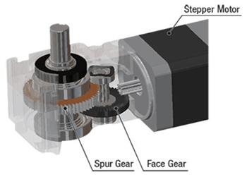 |
Here's how much space you can save with a right-angle gear motor compared to a parallel shaft gear motor.
In general, stepper motor, servo motor, and linear actuator systems address the torque, accuracy, resolution, smoothness, and positioning required by precision applications such as wafer transfer, deposition, etching, and dicing. Brushless speed control motor systems provide compact size, simple control, and speed stability for variable speed applications such as oxidation, photo-resist coating, and wafer polishing. It really depends on the precision you need.
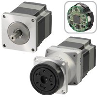
If you want an easier way to build a CMP tool, our AlphaStep AZ Series family of closed-loop stepper motors, hollow rotary actuators, and dedicated smart drivers can meet all requirements above and more. For data monitoring and network control, major protocols like EtherNet/IP, EtherCAT, Profinet, and Modbus RTU are available.
The Result
Here's a video of a rotating arm for a CMP tool that's similar to our customer's design. Both the hollow rotary actuator at the bottom and the geared motor on top are powered by the same AlphaStep AZ Series motor technology, so the same dedicated smart drivers and software can be used to program both axes of motion. This simplifies the design and saves time!
| TIP: What about other axes? | ||||
|
For other semiconductor wafer process applications on a CMP tool, such as the throttle valve and pin lift axes, please see below for some product ideas to minimize footprint.
|
Related article: Simplify Wafer Handling Machine Design with Modular Products from the Same Family
Interested in building a robot arm or a CMP tool yourself?
| Oriental Motor offers plug-and-play solutions that use the same drivers and are easy to set up for the swing arm and end-effector axes. Please contact our experts for a deeper introduction to our products and sizing support. | 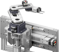 |
