In part 3, we will explain the differences in the structure and rotation principles of brushless motors, and compare them to brushed DC motors and AC motors.
| Brushless Motor Structure and Rotation Principles |
Brushless motors maintain the excellent controllability of DC motors while replacing their brushes and commutator with electronic components.
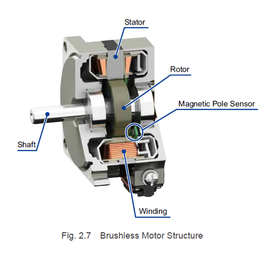
2.2.1 Brushless Motor Structure
The rotor contains permanent magnets, and the stator contains windings, which means the structure reverses the locations of the stator and rotor in the DC motor shown in Fig. 2.1 (previous post). With brushed DC motors, the motor begins rotation once current is supplied to its windings through the commutator and brushes. As the motor rotates, the next set of commutator and brush are energized, thus directing current flow into different windings and continuing the rotation. Since brushless motors create commutation without using brushes or commutator, they require magnetic pole sensors (hall elements, hall effect ICs, etc.) to detect the magnetic pole positions of the permanent magnets, as well as drivers for directing the current to flow through the windings according to the detected magnetic pole positions.
2.2.2. Brushless Motor Rotation Principles
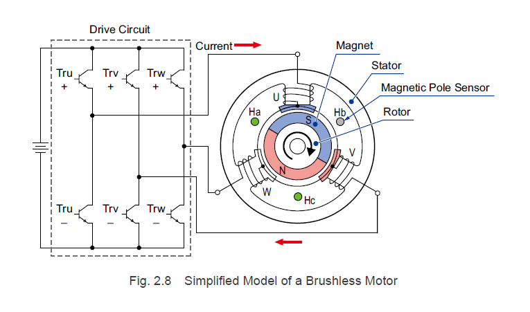
To explain the rotation principles for brushless motors, we will use the simplified three-phase, 2-pole model showing in Fig. 2.8.
With rotor magnets, both the north pole and south pole have a magnetic pole angle of 180°. Magnetic pole sensors Ha, Hb, and Hc are spaced 120° apart, and they detect the north pole of the rotor magnets and output a signal.
With the stator, the phase-U coil, phase-V coil, and the phase-W coil are spaced 120° and are offset from the magnetic pole sensor by 60°.
For each of the stator's phase windings, a south pole is generated in the inner diameter side of the stator when a current flows from the drive circuit to the motor. A north pole is generated in the inner diameter side of the stator when the current flows in the opposite direction. Fig 2.8 shows the state when a current flows from phase-U to phase-V.
For the explanation of the motor rotation principles, let us use the rotation sequence shown in Fig 2.9 and assume that the orientation of the rotor magnets shown in Fig. 2.8 is the initial point (0°).
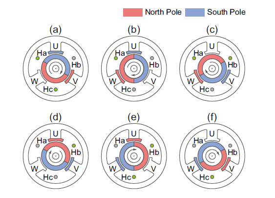
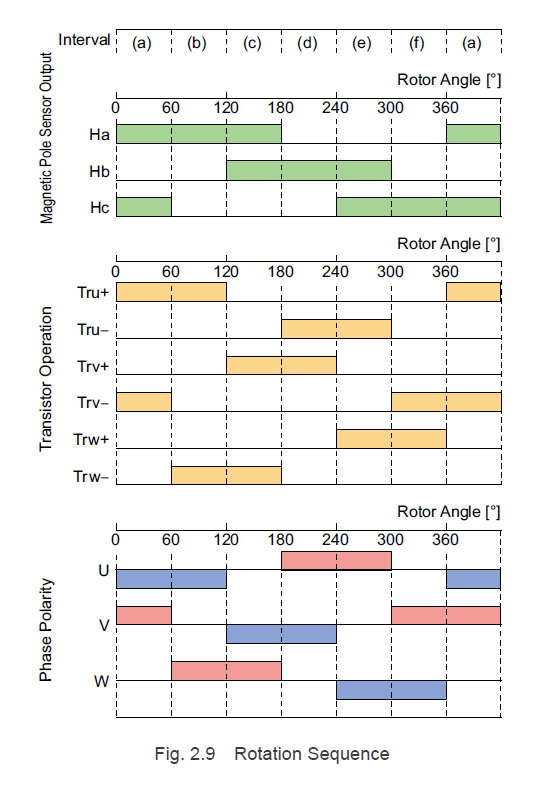
1. In interval (a), magnetic pole sensors Ha and Hc detect the north pole and output a signal. In this case, if transistors Tru+ and Trv= are turned ON, a current flows from the phase-U coil to the phase-V coil in the stator. At this time, the phase-V is magnetized in the north pole (excitation), attracts the south pole, and repels the north pole in the rotor magnets. The phase-U is magnetized in the south pole (excitation) and repels the south pole in the rotor magnets. This causes the rotor to rotate clockwise.
2. In interval (b), which is past 60°, only magnetic pole sensor Ha detects the north pole and outputs a signal. In this case, if transistors Tru+ and Trw- are turned ON, a current flows from the phase-U coil to the phase-W coil in the stator. The phase-U maintains excitation, attracts the north pole, and repels the south pole in the rotor magnets. The phase-W is excited as the north pole and repels the north pole in the rotor magnets. This causes the rotor to rotate clockwise.
3. For each 60° of rotation, the combination of ON and OFF states for magnetic pole sensors Ha, Hb, and Hc changes. For a single rotation of the motor, there are 6 different magnetic pole sensor output combinations, represented by (a) through (f). Through the sequential switching of a determined set of excited phases for each pattern, a rotating magnetic field is continuously generated.
In addition, by changing the way the current flows through the coil for each of the output combinations for magnetic pole sensors Ha, Hb, and Hc, the motor rotation direction can be reversed.
For example, if transistors Trv+ and Tru- are turned ON when only magnetic pole sensor Ha detects a north pole and outputs a signal at interval (b) noted above, a current flows from the phase-V coil to the phase-U coil in the stator. At this time, the phase-U is excited as the north pole, attracts the south pole, and repels the north pole in the rotor magnets. The phase-V is excited as the south pole and repels the south pole in the rotor magnets. This causes the rotor to rotate counter-clockwise.
In summary, brushless motors rotate by directing current flow through the phase coils according to the magnetic pole sensor output signals. The detection of the sensor output signals, as well as the automatic switching of transistors, are handled by a "drive circuit", which is sometimes referred to as a "drive" or "driver".
| TIP: Brushless Motor Currents |
| Direct current is applied to the drive circuits of brushless motors, but an alternating current flows through the motor. For this reason, brushless motors are sometimes called AC synchronous motors. |
2.2.3 Brushless Motor Characteristics
As explained in "2.2.1 Brushless Motor Structure", the stator and rotor positions in brushless motors are the opposite of their positions in DC motors. For this reason, the fundamental speed-torque characteristics for brushless motors exhibit the same sloping characteristics as brushed DC motors, as shown in Fig 2.10, and the motor rotates at a rotation speed that matches the load torque.
If the speed slows down, the torque generated by the motor increases, and a current proportional to the torque flows. If a large current flows, the magnetic force of the permanent magnet is the motor may decrease (demagnetization), and the windings may overheat and experience burnout. In addition, the output element and converter on the drive circuit must be able to handle large currents, which causes the drive circuit to be large and expensive.
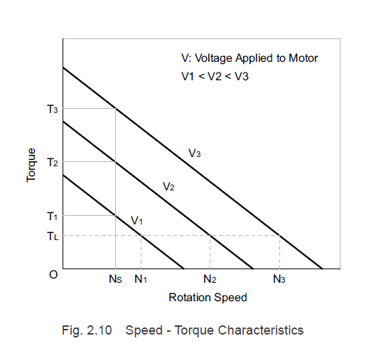
If the speed increases, the torque generated by the motor decreases, and the load torque required for driving decreases, making it unsuitable for use. Operating it at a higher speed increases the noise emitted by the gearhead combined with the motor, and it also causes insufficient gearhead lubrication, which affects the life span.
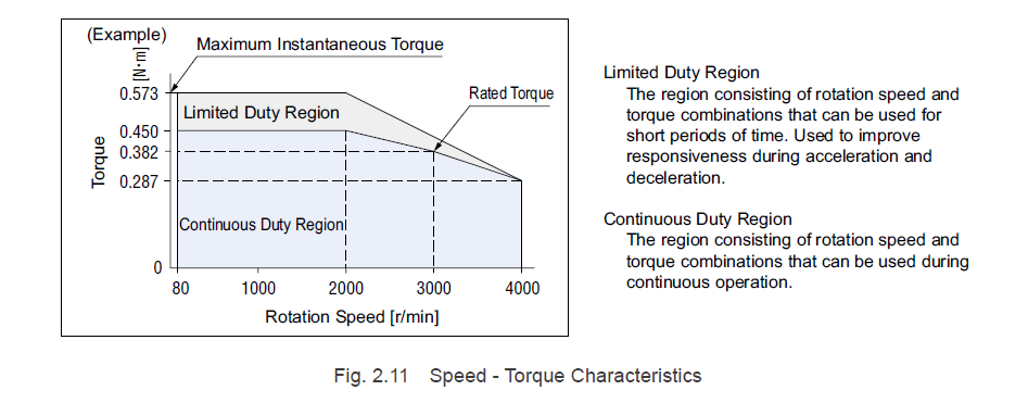
For the above reasons, with brushless motors, the drive circuit limits the maximum current that flows through the motor and maximum rotation speed. Thus, the speed-torque characteristics printed in Oriental Motor's product catalog are similar to Fig. 2.11.
| TIP: Rotor Magnet Demagnetization |
| Permanent magnets are magnetized by applying a strong magnetic field to magnet materials. Conversely, causing excessive current to flow through a motor causes the stator to generate a diamagnetic field, which decreases the magnetic force of the rotor magnets. This is called demagnetization. |
Oriental Motor's motor and driver systems are designed to prevent demagnetization at the current at which the maximum instantaneous torque is generated.
2.2.4 Brushless Motor Features
The features of brushless motors are indicated below.
Compared to DC Motors
- The speed-torque characteristics have the same sloping characteristics as brushed DC motors and have excellent controllability.
- Because there are no brushes or commutator, there is no need to clean the abrasion powder, replace the brushes, or perform other periodic maintenance, giving them a longer life span.
- Since there are no brushes or commutator, there is no electronic noise due to arcs. Switching noise is generated.
- No mechanical acoustic noise (brushes) is generated.
- Magnetic pole sensors and drivers are needed for operation.
- Since the motor rotation speed is detected from the magnetic pole sensor output and feedback control is performed, there is high speed accuracy.
- Because there is feedback control, abnormal behavior can be detected during operation.
Compared to Inverter Controlled Motors and AC Speed Control Motors
- Since the torque is flat from low speed to high speed, the speed ratio is large for all practical purposes.
- If compared at the same output power, the brushless motor is compact and more efficient.
- Can be used with a DC power supply.
- Since the motor rotation speed is detected from the magnetic pole sensor output and feedback control is performed, there is high speed accuracy.
- Because there is feedback control, abnormal behavior can be detected during operation.0
Since brushed DC motors are inexpensive, they are used for various applications where required life span is relatively short. However, for general industrial use, not only are there problems with the life span and maintainability, but there is also a need for a high level of reliability in terms of speed accuracy during operation, malfunction detection, and so on, which has led to increasing popularity of brushless motors. In addition, since the motors are compact, have high output power, and are highly efficient, they are used in devices that need to be compact and lightweight, as well as for battery-powered devices.
Interested in learning more?

|
Previous Post
|
Next Post
|


Learn more about Oriental Motor's 
Subscribe (top right corner) to receive monthly updates!