AC motors are the workhorses of industrial automation. They're robust, easy to use, and offer a wide product breadth. What do you do if they stop working, and you don't have a spare?
Of course, you can always buy a new motor, or contact the motor manufacturer's technical support team. However, most issues can be diagnosed pretty quickly.
Here are some common problems with AC motors that our team frequently hears about:
- The motor does not run
- Start and stop / intermittent operation
- Unable to control the rotation direction
- Unable to control movement, speed...etc.
Typically, for a standalone AC motor, these issues are caused by faulty wiring.
Follow along with me as I go through a troubleshooting process and share tips from our technical support team. Don't worry. We'll skip the default questions and assume that the power is on.
| Troubleshooting Example | "My AC motor doesn't run." |
When a customer calls our technical support team and complains that their motor doesn't run, our engineers would first verify if the capacitor is wired properly. Once we verify the wiring, then we can move on to other checks.
Why is the capacitor so important?
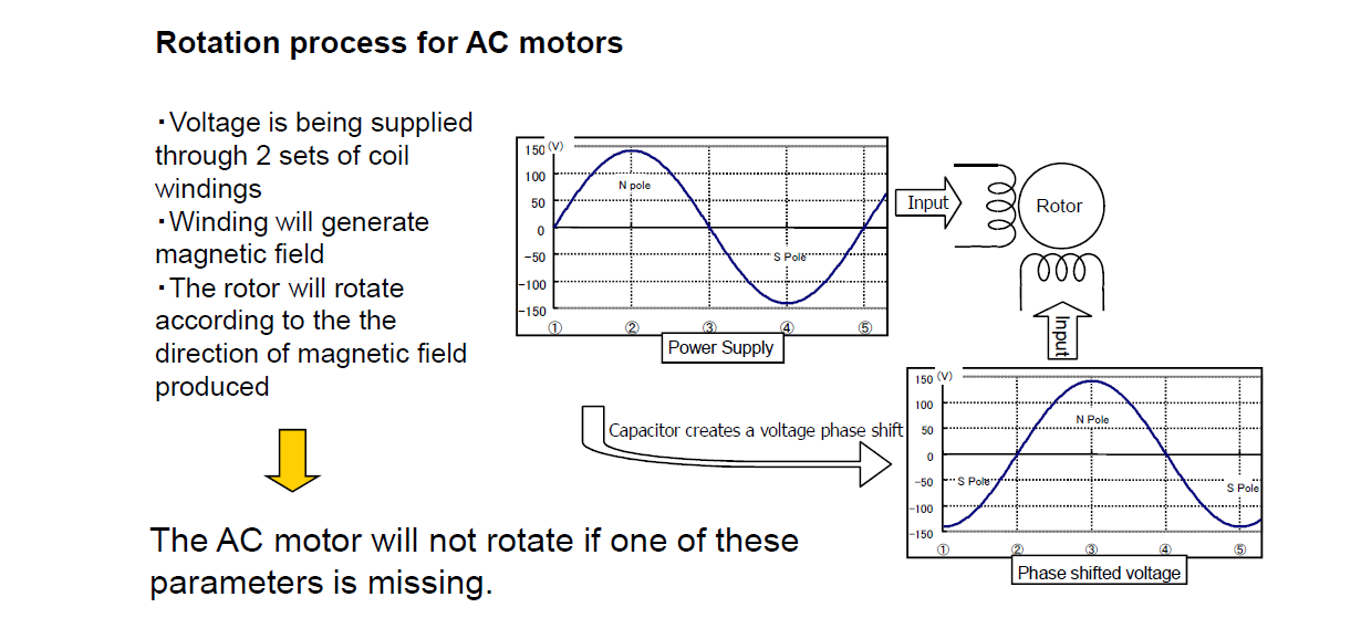
A phase shift creating two phases from the power supply is created when a capacitor is used with a single-phase permanent-split-capacitor motor. For this type of AC motor to start, it needs the primary voltage from the power supply and a slight boost from the secondary "phase shifted voltage" generated by the capacitor connected between the power supply and the motor (see below).
| FYI | For more information, please read our Engineering Note: What Does a Capacitor Do? |
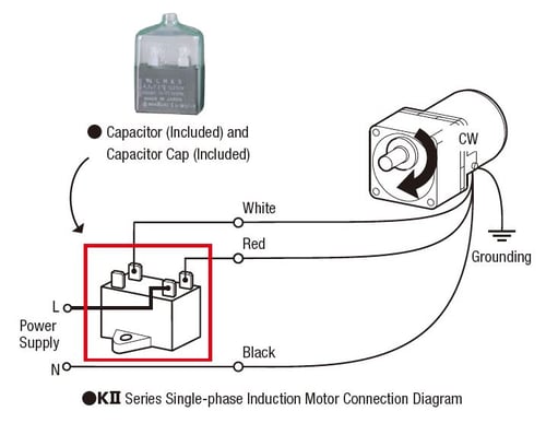
To verify the wiring for a single-phase AC permanent-split-capacitor motor, make sure:
- Black is always connected to "N" (neutral).
- Connect the other two wires, typically red and white, to opposite terminals of the capacitor.
- Connect "L" (live) to the white or red side of the terminal to determine the rotation direction.
 |
 |
If you're not comfortable working with electricity, please ask for help.
If the motor still doesn't run after verifying the wiring...
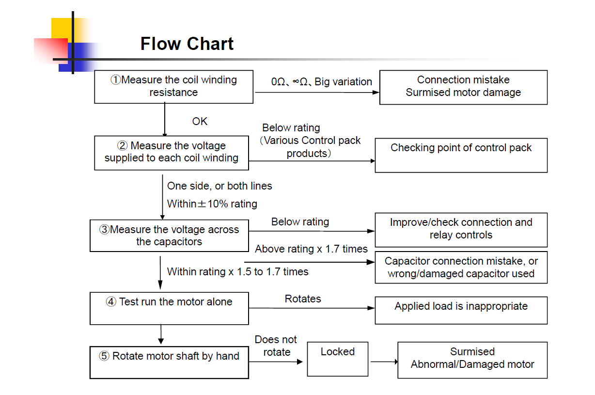
At this point, our technical support team recommends following the flow chart to perform additional checks on coil winding resistance, power supply voltage, load, and bearing.
![]() Measure the coil winding resistance
Measure the coil winding resistance
A resistance check on the motor windings can reveal if the windings are bad. Sometimes, the motor winding could deteriorate due to excessive current or heat.
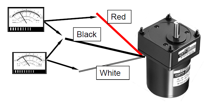
To perform the resistance check, you'll need an ohmmeter or a multimeter. Measure across each pair of wires, then compare the values. If you measure each pair of wires as shown below, the measured values should be equal or very close to each other.
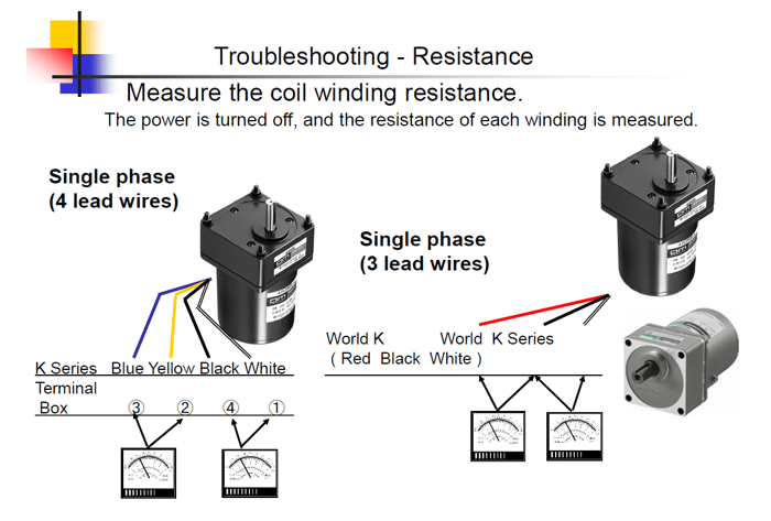
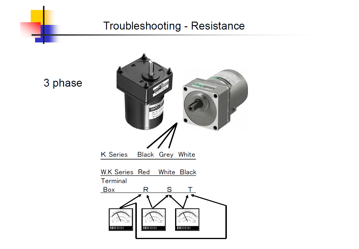
For 3-phase motors, measure across each pair of wires, such as in the image below. The measured values should be the same or very close to each other.
To better understand why the measured values are what they are, let's look at the internal rotor and stator winding diagrams of single and three-phase motors.
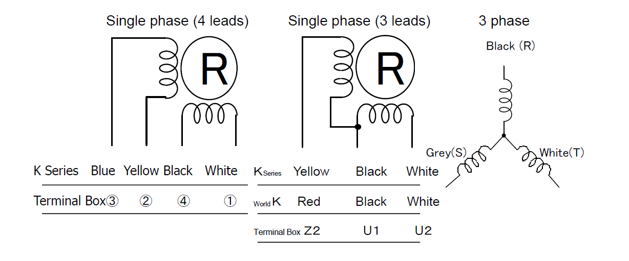
Refer to the left diagram for the 4-lead motor. If we measured blue and yellow wires for resistance, and then measured black and white wires for resistance, we're measuring exactly half of the winding each time, therefore the measured values should be the same.
For three-phase motors, we're measuring 2/3 of the winding at a time.
The resistance value varies with different motors. For the exact resistance value (ohms) that you should measure for your motor, please contact our technical support team with your part number.
If the motor resistance checks out and the motor still doesn't run, you can also perform a resistance check on the extended contact points on any connected relays or switches to verify if they're working as they should. Sometimes, the motor might be fine, but bad switches or relays would prevent the motor from receiving power.
Make sure to turn off the power supply before performing these checks.
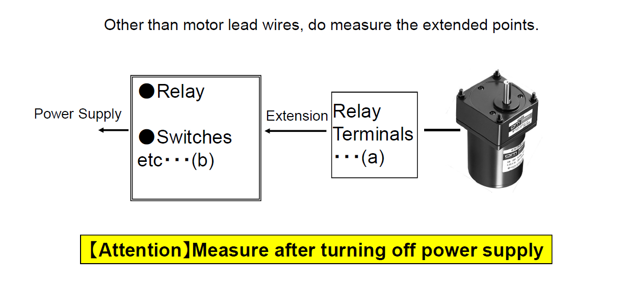
Understanding the results...
Is the resistance too high (kΩ) or above? Is the resistance too low (1Ω or below)?
If so, then this means that the motor has been damaged. If this is measured at location (a) above, then the motor winding's bad. If this is measured at location (b) and not (a), then there's a problem with the relays or switches.
![]() Measure the voltage supplied to each coil winding
Measure the voltage supplied to each coil winding
If the motor checks out, then move on to the voltage check. Turn on the power supply and measure the input voltage with a voltmeter or a multimeter. Measure the value at the terminal/relay contacts that are the closest to the motor. If measuring a speed control motor, the speed potentiometer should be at its maximum setting.
Understanding the results...
Is the input voltage within +/-10% of the rated voltage?
If the input voltage is not within +/-10% of the rated voltage, then it is determined that there's a wiring error (or incorrect voltage). If the voltage is too high, there will be an increase in vibration and a higher generation of heat, which may trip the built-in overheat circuit and stop the motor from operating until it cools down. If the voltage is too low, the motor may not meet its specifications.
![]() Measure the voltage of the capacitor* (single-phase only)
Measure the voltage of the capacitor* (single-phase only)
This step checks if the capacitor is bad or miswired. With a voltmeter or multimeter, measure the voltage between capacitor terminals on opposite ends 1 and 2 (see diagram below). Please measure by the terminal or relay contacts nearest to the motor.
Since capacitors can be replaced easily, our team typically replaces the capacitor for this step. If you cannot find the exact capacitor, use a capacitor with the same voltage rating and similar capacitance. However, for long-term usage, always use the recommended capacitor.
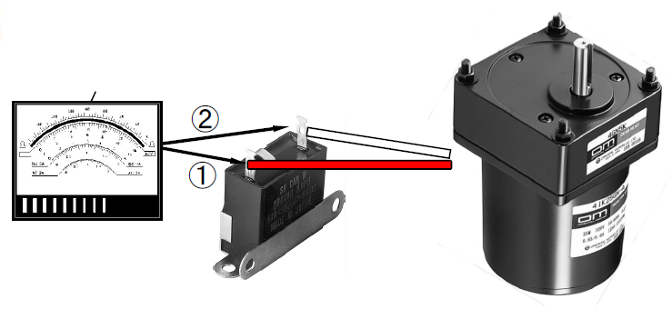
Understanding the results...
Is the measured value 1.5~1.7x of the rated voltage?
If the measured value is less than 1.5x of the rated voltage, either the wrong capacitor has been used, or the capacitor is damaged.
If the measured value is much below the rated voltage (or close to 0v), the capacitor is not functioning properly. Please check the connection between the motor and the capacitor.
If the measured value is twice the rated voltage, the capacitance value may not be correct.
| FYI | For more information, please read our Engineering Note: 3 Ways to Troubleshoot AC Motors with a Circuit Tester |
![]() Test run the motor alone
Test run the motor alone
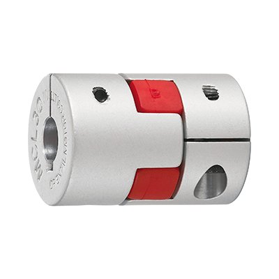
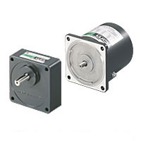
The key in this step is to narrow down and isolate the issue to a specific cause by experimenting. Sometimes, an excessive load can stall the motor and make it seem like it's not running. An overheated motor also does not rotate due to a built-in thermal protection circuit. A loose coupling, a damaged bearing, or even an unreleased electromagnetic brake can prevent motor rotation, so it's important to isolate the issue so you're not wasting time troubleshooting the wrong problem.
 |
 |
 |
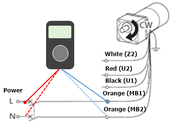
The same multimeter test methods shown above can also be used at this step. Let's say you have isolated the issue to the motor, but the motor's electromagnetic brake is not releasing even when you are absolutely sure that the wiring is correct. In this case, you may have broken lead wires. A resistance check method can be used to confirm this.
To verify if the lead wires for the electromagnetic brake are damaged or disconnected internally, measure the resistance for continuity between power supply (L) and the orange (MB1) AND between power supply (N) and the orange (MB2). Be sure to turn the power off.
Understanding the results...
Does the motor run by itself?
If the motor can run successfully by itself, great! To determine which component is causing the issue, add back the components one by one and re-test. For example, add the gearhead first, then the coupling, then the load. Once the issue occurs again, stop and troubleshoot the component you just added.
![]() Rotate the motor shaft by hand
Rotate the motor shaft by hand
This is an old-school method to check for motor ball bearing damage. The assumption here is that if you cannot even rotate the motor shaft by hand (without load or gearhead attached), then the ball bearing inside the motor case is bad. Sometimes, a damaged ball bearing in the gearhead can also prevent rotation. Typically, the ball bearing inside the gearhead breaks before the motor bearing since it's directly supporting the load.
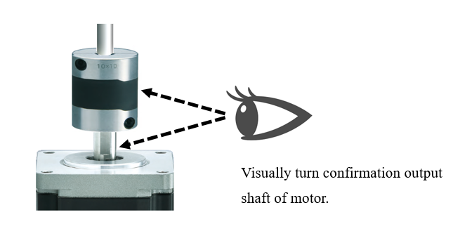
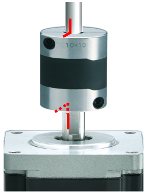
If it's difficult to see, mark the fastened components with a straight line like below.
 |
 |
If any component is loose, re-fasten or re-tighten, then test again.
Understanding the results...
Can you rotate the motor shaft by hand?
If the output shaft can be rotated in either direction manually, then that means the bearings are good. You should not feel a lot of friction on the motor shaft. However, the gearhead shaft could be difficult to turn by hand (depending on the gear ratio or size).
If the motor still doesn't work by now, it's definitely time to replace it.
Please contact our technical support team for more troubleshooting tips
or assistance with replacements and upgrades.
For more troubleshooting posts, such as for stepper motors, please subscribe to our newsletter.
Disclaimer: This article provides troubleshooting tips, but only qualified professionals should perform the work. If you're not qualified, please contact our technical support team. Oriental Motor is not liable for any injuries that can potentially happen from performing the work.
