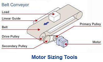
Which type of electric motor do you size for your conveyor, XYZ table, or robot? Before you select one, you must understand the characteristics of each type of motor in the market.
Types of Electric Motors
There are two obvious types of electric motors as determined by input voltage: AC (Alternating Current) or DC (Direct Current).
While AC motors use alternating current to power a series of wound coils, DC motors use direct current to power either carbon brushes or electrical commutation. DC motors are generally more efficient and compact than AC motors.
It's not only important to understand the differences between the characteristics of AC and DC motors but also the specific types within these categories.
Now let's dig deeper into AC and DC motors.
|
Ideal for Constant Speed: AC Motors |
AC motors can be separated into four main categories: shaded-pole, split-phase, capacitor-start, capacitor-start/capacitor-run, and permanent split capacitor. Since Oriental Motor only manufactures permanent split capacitor type AC motors from 1/2 HP down to 1/750 HP, we will generally cover this segment in more detail.
Each type of PSC motor is similar in structure. There are wound coils in the stator and a squirrel cage rotor is used for rotation. Capacitors are required for single-phase motors to generate a polyphase power supply. These motors are very easy to control and require no driver or controller to operate. Minor differences change the characteristics of the basic AC induction motor to suit different performance needs, such as various types of brakes.
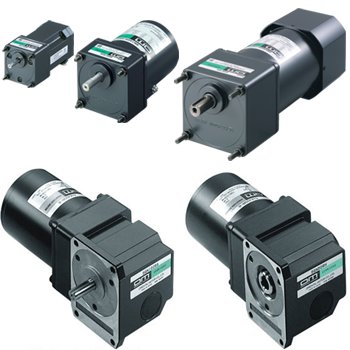
| Different Types of AC Motors |
Induction Motors / Asynchronous Motors
Induction motors are the most common and are rated for continuous duty operation for a wide range of output power from a fraction to thousands of horsepower. They're considered "asynchronous" motors due to the existence of a lag, or slip, between the rotating magnetic field produced by the stator and its rotor. The reason why they're called "induction" motors is that they operate by inducing a current onto the rotor. Since there's no friction besides the ball bearings, they offer an overrun of approximately 30 revolutions after power is removed (before gearing).
The below image describes the design and construction of an induction motor.
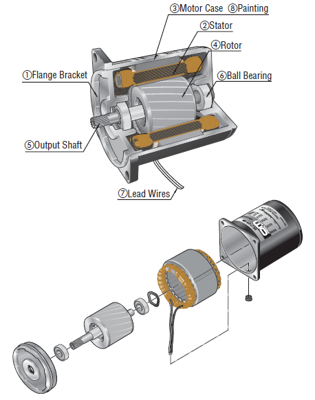 |
① Flange Bracket |
How Do They Work?
When the motor is powered, it generates a rotating magnetic field in the wound stator. By Faraday's Law of electromagnetic induction, current is induced onto the rotor, and the magnetic field created by the induced current interacts with the rotating magnetic field to produce rotation. Its characteristics can be further understood by Lenz's Law and Fleming's Left Hand and Right Hand Rules. However, overrun, depending on load inertia, can be up to 30 revs. For anyone who wants to know more, here's a blog post for more background and technical information on AC induction motors.
|
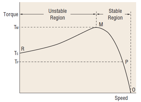
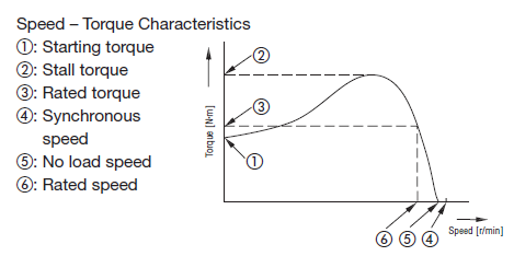
Speed-torque curve depicts expected motor performance A motor's performance is plotted on a speed-torque curve. An AC induction motor will start from zero speed at torque "Ts", then gradually accelerate its speed past the unstable region, and settle on "P" in the stable region where the load and torque are balanced. Any changes to its load will cause the position of "P" to move along the curve, and the motor will stall if it operates in the unstable region. Each motor has its own speed torque curve and a "rated torque" specification. |
 |
Induction motors are robust and can be used for a variety of general-purpose applications where continuous duty is necessary, and stop accuracy isn't critical. Single-phase motors are offered for fixed speed requirements. Variable speed requirements can be met by combining a three-phase induction motor with a VFD (variable frequency drive) or a single-phase motor with a TRIAC controller. Some manufacturers also offer wateright, dust-proof motors by enclosing an induction motor in a sealed case.
Reversible Motors
Reversible motors, by definition, can reverse on the fly and are ideal for start/stop operation. A reversible motor is similar to an induction motor but with a friction brake and more balanced windings. Due to a friction brake mechanism, its overrun is significantly reduced after power is removed. The motor winding is also more balanced to increase its starting torque for start/stop operation.
Due to the additional heat generated from reversible motors, their recommended duty cycle is only 30 minutes or 50%. An example of a reversible motor application is an indexing conveyor that isn't too demanding on throughput or stop accuracy.
How Do They Work?
|
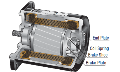
A friction brake mechanism is installed at the rear of a reversible motor. The coil spring applies constant pressure to allow the brake shoe to slide toward the brake plate. When the motor stops, the friction from the brake reduces the motor overrun from ~30 revs to ~6 revs. The brake force produced by the brake mechanism of an Oriental Motor's reversible motor is approximately 10% of the motor's output torque. |
|
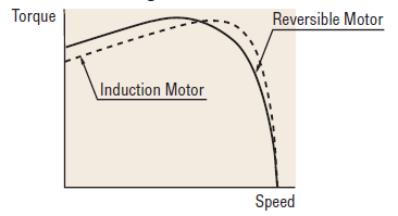 |
The graph shows the difference between speed-torque curves of an induction motor vs a reversible motor. A reversible motor has highter starting torque characteristics than an induction motor. |
Electromagnetic Brake Motors
Electromagnetic brake motors combine either a three-phase induction motor or a single-phase reversible motor with a built-in power-off-activated electromagnetic brake. Compared to reversible motors, these motors offer an overrun of just 2~3 revolutions (before gearing) and can be used up to 50 times a minute. These motors are designed to hold their rated load during a vertical operation, or just to lock the motor in place when power is removed.
The brake mechanism inside an electromagnetic brake motor is more advanced than the reversible motor. Instead of a brake shoe and a coil spring that constantly applies pressure, the electromagnetic brake is engaged and disengaged by an electromagnet and spring mechanism.
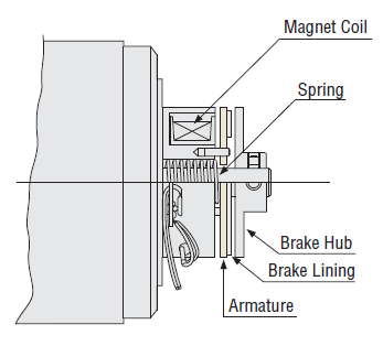
How Do They Work?
This is a power-off-activated type of brake, which means the brake engages and stops the motor when power is removed from its lead wires. When voltage is applied to the magnet coil during normal operation, it becomes an electromagnet and attracts the armature, with the brake lining, against the force of the spring and away from the brake hub, thereby releasing the brake and allowing the motor shaft to run freely. When no voltage is applied, the spring presses the armature onto the brake hub and holds the motor's shaft in place, thereby actuating the brake.
Electromagnetic brake motors are used in vertical applications where the load must be held, or in applications where the load must be locked into position when the power is removed.
Torque Motors
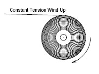
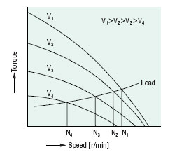
Torque motors are designed to provide high starting torque and sloping characteristics (torque is highest at zero speed and decreases steadily with increasing speed), along with operating over a wide speed range. Due to their ability to alter torque output based on input voltage, they provide stable operation under a locked rotor or stall condition, such as a winding/tensioning application.
How Do They Work?
A torque motor can vary its torque and speed according to the load torque.
|
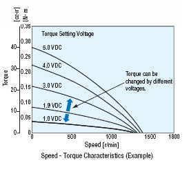
Easy torque adjustment for tensioning
|
 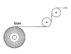 |
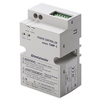
A voltage controller, such as the TMP-1, can be used to vary voltage to a torque motor to control its torque. Just like a speed controller, a voltage can be set using a potentiometer or external DC voltage.
 |
 |
 |
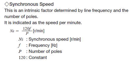
Synchronous Motors
Synchronous motors are called "synchronous" because they use a special rotor to synchronize their speed with the input power frequency. For a 4-pole synchronous motor running at 60 Hz power, it will rotate at 1800 RPM (AKA "synchronous speed"). My earliest memory of a synchronous motor application was someone using it to drive the clock hands of a tower clock.
How Do They Work?
This type of motor offers a bit more responsiveness and precision on the speed. Its synchronous speed is determined by how many poles the motor has and the frequency of input voltage.
 |
 |
Another type of synchronous motor called the low-speed synchronous motor provides highly precise speed regulation, low-speed rotation, and quick bi-directional rotation. These motors actually use the rotor and stator laminations from a stepper motor design but are driven by AC power supply. Therefore, they're more responsive, but the higher number of poles also decreases the synchronous speed to 72 RPM at 60 Hz. Low-speed synchronous motors can stop within 0.025 seconds at 60 Hz if operated within the permissible load inertia.
The basic construction of low-speed synchronous motors is the same as that of stepper motors. Since they can be driven by an AC power supply and offer superb starting and stopping characteristics, they are sometimes called "AC stepper motors".
|
Ideal for Speed Control: DC Brushed and Brushless Motors |
DC motors are generally much smaller than AC motors and use direct current to power the carbon brushes and commutator, or electrically commutate the windings with a driver. DC motors are about 30% more efficient than AC motors since they do not have to induce current to create magnetic fields. Instead, they use permanent magnets in the rotor. Oriental Motor's DC motors are generally fractional horsepower; up to 400 watts (1/2 HP).
Within DC motors, there are two main types: brushed and brushless. While brushed motors are designed for general-purpose variable speed applications, brushless motors are designed for more advanced requirements.
| Different Types of DC motors |
Brushed Motors
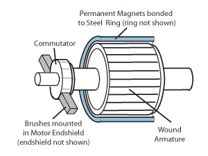
The brushes and commutator inside a brushed motor mechanically commutate the motor windings as it runs, and it continues rotation as long as its power supply is connected. Brushed motors are easy to control (by varying the voltage for speed and torque), but the brushes require periodic maintenance and replacement and therefore have an estimated lifespan of 1,000~1,500 hours (more or less due to operating conditions). While they're considered more efficient than AC motors, they suffer losses in efficiency compared to brushless motors due to resistance in the winding, brush friction, and eddy-current losses.
Brushed motors are offered in multiple types: permanent magnet brush type, shunt-wound type, series-wound type, and compound-wound type. A typical application for a brushed motor includes RC cars and windshield wipers.
Since Oriental Motor doesn't manufacture brushed motors, we offer limited information on brushed motors.
Brushless Motors
Brushless motor systems offer better speed control and performance than brushed motors due to electrical commutation and closed-loop feedback but require drivers to work. This raises the overall cost per axis, but it may be a necessary cost for applications requiring more advanced speed control features or closed-loop functions, such as continuous duty conveyors requiring multiple speeds or status monitoring.
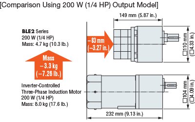
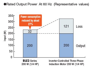
Brushless motor and driver systems are often compared with AC motor and VFD systems for their advantages in size, weight, and efficiency especially for applications such as conveyors or mobile robotics.
Here's a comparison between a 200 W AC motor and VFD vs a BLE2 Series brushless motor and driver.
 |
 |
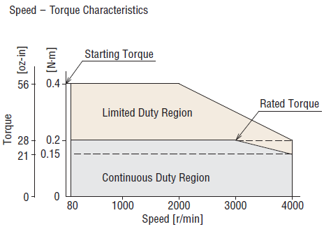
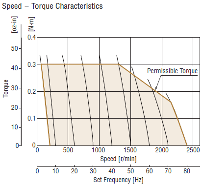
We also show a speed torque curve of a brushless motor system compared to an AC motor and VFD system of equivalent frame size.
| Brushless Motor + Driver | AC Motor + VFD |
 |
 |
How Do They Work?
Compared to a brushed motor, a brushless motor simply requires a driver to understand its feedback signals and commutate the motor windings in the right sequence and timing.
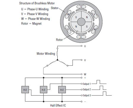
| For Oriental Motor's brushless motors, a three-phase winding in a "star" connection is used on a radially segmented permanent magnet rotor. A built-in Hall effect sensor IC or optical encoder sends signals to the drive circuit to determine rotor position for the purpose of phase excitation timing. | 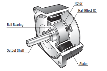 |
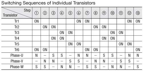
On brushless motors with Hall effect IC, three Hall effect sensors are placed within the stator at 120 degrees apart and send digital signals as they sense the north and south poles go by as the rotor rotates. These signals tell the driver what speed the motor is running at and when to energize the next set of winding coils at exactly the right time.
 |
 |
Want to know more? Learn about the differences between brushed vs brushless motors.
Oriental Motor's brushless motor systems are paired with their own dedicated drivers for guaranteed specifications and quick setup. Various gearing options are offered for flexibility. Closed-loop feedback is done by either encoder or hall-effect sensors, and each driver offers different features and functions to suit various applications.
The Brushless Motor Advantage
| Advantages vs Brushed Motors | Advantages vs AC Motors |
|
|
|
Ideal for Positioning: Stepper Motors |
Stepper Motors
Technically, brushless motors also include stepper motors, which are designed for positioning applications due to their high pole count, holding torque, and superior stop accuracy. Compared to 10 or 12 poles on a brushles motor rotor, a stepper motor rotor has at least 50 poles or even 100 poles. Similar to a brushless motor, a stepper motor requires a driver to operate. Unlike a brushless motor, a stepper motor can operate without feedback.
Also, duty cycles for open-loop stepper motor systems must be limited since they generate high heat. Generally, stepper motors use full current at all times, while brushless motors only use what it needs according to the load, speed, or acceleration/deceleration parameters. Oriental Motor provides 2-phase (1.8°) and 5-phase (0.72°) motors as well as unipolar and bipolar constant current chopper drivers.
 |
A stepper motor's precise stopping ability comes from a toothed and magnetized rotor and a toothed electromagnetic stator. A standard 1.8° stepper motor has 50 poles from 50 teeth in the rotor and 8 poles in the stator. |
How Do They Work?
Like a brushless motor, a stepper motor also requires a driver to electrically commutate its windings. With higher pole count, comes better control. Using a two-phase excitation method for maximum torque, a driver excites two motor phases at a time and operates by pulses and steps. This means that each command pulse received by the driver will make the motor take a small "step", and the frequency of these command pulses determines the motor speed. Also, a stepper motor driver can energize specific poles in the motor, generate holding torque at standstill, and hold the rotor at specific positions.
Imagine stopping at position "1" in the simplified 4-step rotation diagram below. If the driver can provide a steady amount of current and energize phases "A" and "B" continuously, the motor will hold at position "1". If the driver excites the next two phases, then the motor will move to the next step. If the driver follows the step sequence and switches faster, the stepper motor will seem like it's rotating continuously.
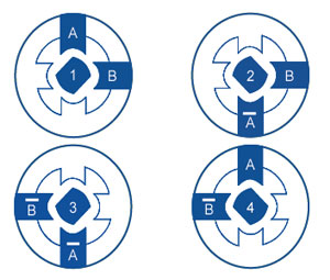
In the real world, a 2-phase standard 1.8° stepper motor moves a quarter of a tooth pitch on a 50 tooth rotor for every command pulse its driver receives and therefore needs 200 steps to rotate one full revolution. The ability to generate holding torque at standstill helps to maintain stop position accuracy.
Open-loop stepper motors may suffice for general repeated positioning applications. However, closed-loop stepper motors are available for advanced positioning applications requiring higher reliability and efficiency.
|
|
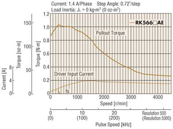
A stepper motor's speed torque curve is typically downward sloping; with the highest torque occurring during low speed, which means that it can be used for acceleration and deceleration. Unlike a brushless motor system, a stepper motor does not have a limited-duty region. |
If you'd like to learn more, I have written separate notes about stepper motors. Please enjoy.
Learn about the differences between hybrid, PM, and VR stepper motors
Learn more about the differences between servo motors and stepper motors
| Motor Selection Tip: Rule of Thumb |
|
This blog post provides a general understanding of the many types of AC/DC motors in the market. In addition to performance differences, quality, cost, product breadth, lead times, and support can also be deciding factors. Finding a quality motor supplier that can guarantee performance, provide expert support for a wide range of products, and ship reliably can also be important.
Ready for a little practice? Which type of motor would you use for these applications?
Click the application GIFs below to see the recommended motors for these applications.
| Washdown Conveyor | XYZ Table |
 |
 |

Need immediate answers? Contact our team!